Fluke CNX v3000 Manual - Page 29
Diode Test
 |
View all Fluke CNX v3000 manuals
Add to My Manuals
Save this manual to your list of manuals |
Page 29 highlights
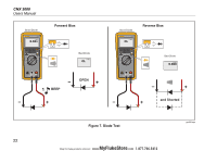
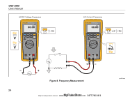
Diode Test Warning To prevent possible electrical shock, fire, or personal injury, disconnect power and discharge all high-voltage capacitors before you measure resistance, continuity, capacitance, or a diode junction Do a diode test on diodes, transistors, silicon controlled rectifiers (SCRs), and other semiconductor devices. The function sends a current through the semiconductor junction and then measures the voltage drop across the junction. A good silicon junction drops between 0.5 V and 0.8 V. To do a diode test on a diode out of circuit, set up the Product as shown in Figure 7. For forward-bias measurements on a semiconductor component, put the red test lead on the positive terminal of the component and put the black test lead on the negative terminal of the component. In a circuit, a good diode has a forward-bias measurement of 0.5 V to 0.8 V. A reverse-bias measurement includes the resistance of other pathways between the probes. A short beep sounds if the diode is good (
-
 1
1 -
2
-
3
-
4
-
5
-
6
-
7
-
8
-
9
-
10
-
11
-
12
-
13
-
14
-
15
-
16
-
17
-
18
-
19
-
20
-
21
-
22
-
23
-
 24
24 -
 25
25 -
 26
26 -
 27
27 -
 28
28 -
 29
29 -
 30
30 -
 31
31 -
 32
32 -
 33
33 -
 34
34 -
35
-
36
-
37
-
38
-
39
-
40
-
41
-
42
-
43
-
44
-
45
-
46
-
47
-
48
-
49
-
50
 |
 |
