Contents
SUBJECT
PA GE
Prednsta%Son Require,remits
2
Electrical Requirements
2
Exhaust System Requirements
2-3
Gas Supply Requirements
3
Location of "four Dryer
4
Mobile Home Installation
5
Roughdn Dimensions
5-6
Unpacking
6
Reversing Door Swing
6
Electrical Insta%8on
7
Grounding Requirements
7
Electrical Connections--3-wire
7
Electrical Connections--4-wire
8
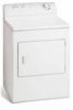
Installation
8
Replacement Parts
8
PREdNSTALLATION
REQUIREMENTS
Tools and Materials Required for Installation: I. Phillips head screwdriver. 2. Channel-lock adjustable pliers. ;3. Carpenter's level.
4. Flat or straight blade screwdriver, 5. Duct tape. 6. Rigid or flexible metal 4 ir_ch (10,2 cm) duct, 7. Vent hood.
8. Pipe thread sealer (Gas). g, Plastic knife.
ELECTRICAL REQUIREMENTS
i
ELECTR/CDryer
CIRCUIT o Individual 30 amp branch circuit fused with 30 amp. time delay fuses or circuit breakers_
Use separately fused circuits for washers and dryers, and DO NOT operate a washer and a dryer on the same circuit
POWER SUPPLY - 3 wire, 240 volt, single phase, 60 Hz, Alternating Current. (Canada -240 volt, single phase, 60 Hz, Alternating Current.)
POWER SUPPLY CORD KIT - The dryer MUST employ a 3
1
2
3
4
5
6
7
8
9
10
11
12
13
14
15
16
17
18
19
20
21
22
Contents
SUBJECT
PA
GE
Prednsta%Son
Require,remits
2
Electrical
Requirements
2
Exhaust System Requirements
2-3
Gas
Supply Requirements
3
Location
of "four
Dryer
4
Mobile
Home
Installation
5
Roughdn Dimensions
5-6
Unpacking
6
Reversing Door Swing
6
Electrical Insta%8on
7
Grounding
Requirements
7
Electrical
Connections--3-wire
7
Electrical
Connections--4-wire
8
Installation
8
Replacement
Parts
8
PREdNSTALLATION
REQUIREMENTS
Tools
and
Materials
Required
for
Installation:
I.
Phillips head screwdriver.
2.
Channel-lock
adjustable
pliers.
;3.
Carpenter's
level.
4.
Flat or straight
blade screwdriver,
5.
Duct tape.
6.
Rigid or flexible
metal 4 ir_ch (10,2 cm) duct,
7.
Vent hood.
8.
Pipe thread
sealer (Gas).
g,
Plastic knife.
ELECTRICAL
REQUIREMENTS
i
ELECTR/CDryer
CIRCUIT
o Individual
30
amp
branch
circuit
fused
with
30 amp.
time
delay
fuses
or circuit
breakers_
Use separately
fused
circuits
for
washers
and
dryers,
and
DO
NOT
operate
a washer
and
a dryer
on
the
same circuit
POWER
SUPPLY
- 3 wire,
240
volt,
single
phase,
60
Hz, Alternating
Current.
(Canada
-240
volt,
single
phase,
60 Hz, Alternating
Current.)
POWER
SUPPLY
CORD
KIT
- The dryer
MUST
employ
a 3<onductor
power
supply
cord
NEMA
10o30
type
SRDT rated
at
240
volt
AC
minimum,
SO
amp,
with
S
open
end
spade
lug
connectors
with
upturned
ends
or closed
loop
connectors
and
marked
for
use with
clothes
dryers
WARNING
-
Risk
of
Shock.
Appliance
grounded
to
neutral
conductor
through
a
link_
Grounding
through
the
neutral
link
is
prohibited
for
(1) New
branch
circuit
installations
(2) mobile
homes;
(3) recreational
vehicles;
and
(4) areas where
local codes
do not permit
grounding
through
the
neutral,
(!)
disconnect
the
link
from
the
neutral,
(2)
use
grounding
terminal
or lead
to
ground
appliance
in
accordance
with
local codes
and
(S) connect
neutral
terminal
or lead
to
branch
circuit
neutral
in usual
manner
(if
the
appliance
is to
be
connected
by
means
of
a
cord
kit,
use 4<onductor
cord
for
this
purpose)
USE COPPER CONDUCTOR
ONLY. The dryer
MUSTemploy
a 4-conductor
power
supply
cord
NEMA
14-30
type
SRDT or
ST (as
required)
rated
at
240
volt
AC
minimum,
30
amp.
with
4 open
end
spade
lug connectors
with
upturned
ends
or closed
loop
connectors
and
marked
for
use
with
clothes
dryers
See
ELECTRICAL
CONNECTIONS
FOR A 4-WIRE
SYSTEM
(Canada
- 4-wire
power
supply
cord
is installed
on
dryer_)
OUTLET
RECEPTACLE-
NEMA
10-30R
receptacle
to
be
located
so
the
power
supply
cord
is accessible
when
the
dryer
is in the
installed
position
(Canada
-
NEMA
14-30R
receptacles)
3
WIRE GROUNDED
NEUTRAL
120-240
VOLT 60 CYCLE
MAIN
FUSE BOX
30 AMP
DELAYED ACTION
FUSE5
OR CIRCUIT
BREAKER
NEUTRAL
WIRE
OUTLET
RECEPTACLE
(COPPER)
SUBJECT
TO LOCAL
REGULATIONS
NEMA
lOoSeR (COPPER)
GAS Dryer
CIRCUIT-
Individual
I B amp_
branch
circuit
fused
with
a
15
amp.
maximum
time
delay
fuse or circuit
breaker_
POWER
SUPPLY-
3 wire,
120
volt
single
phase,
60
Hz, Alternating
Current
POWER
SUPPLY
CORD
-
The dryer
is equipped
with
a 120 volt
3-wire
power
cord
NOTE:
Do not
under
f
_, _-_
any
circumstances
1
remove
grounding
prong
from
plug.
_
GROUNDING
PRONG
EXHAUST
5 YSTEM
REQUIREMENT5
Use only
4 inch
(102
cm)
diameter
(minimum)
rigid
or flexible
metal
duct
and
approved
vent
hood
which
has a swing-out
damper(s)
that
open
when
the
dryer
is in operation_
When
the
dryer
stops,
the
dampers
automatically
close
to
prevent
drafts
and
the
entrance
of
insects
and
rodents.
To avoid
restricting
the
outlet,
maintain
a
minimum
of
12
inches
(30.5
cm)
clearance
between
the
vent
hood
and
the
ground
or any other
obstruction
The
following
are
specific
requirements
for
proper
and
safe
operation
of
your
dryer.
Failure
to
follow
these
instructions
can
create
excessive
drying
times
and
fire
hazards.
Do
not
use
plastic
flexible
duct
to
exhaust
the
dryer
Excessive
lint
can
build
up
inside
exhaust
system
and
create
a fire
hazard
and
restrict
air
flow_
Restricted
air
flow
will
increase
dryer
times
If your
present
system
is made
up
of plastic
duct
or metal
foil
duct,
_olace
it with
a rigid or flexible
metal duct
Ensure
the
present
duct
is
free
of
any
lint
prior
to installing
dryer
duct.
__-
Risk
of
Fire
- A clothes
dryer
produces
combustible
lint
If the
dryer
is not
exhausted
outdoors,
some
fine
lint
will
be
expelled
into
the
laundry
area
An accumulation
of lint
in any area of
the
home
can
create
a health
and
fire
hazard.
The
dryer
must
be
connected
to
an exhaust
outdoors.
Regularly
inspect
the outdoor
exhaust
opening
and
remove
any
accumulation
of
lint
around
the
outdoor
exhaust
opening
and
in the
surrounding
area
Do
not
allow
combustible
materials
(for
example:
clothing,
draperies/curtains
paper)
to
come
in contact
with
exhaust
_stem
The dryer
MUSTNOTbe
exhausted
into
a chimney,
a wall,
a
ceiling,
or any concealed
space
of
a building
which
can accumulate
lint,
resulting
in a fire
hazard
Exceeding
the
length
of duct
pipe
or number
of elbows
allowed
in
the
"MAXIMUM
LENGTH"
charts
can
cause
an
accumulation
of
lint
in the
exhaust
system_
Plugging
the
system
could
create
a fire
hazard,
as well
as increase
drying
times_
Do
not
screen
the
exhaust
ends of
the
vent
system,
nor
use
any
screws
or
rivets
to
assemble
the
exhaust
system.
Lint
can
become
caught
in the
screen,
on
the
screws
or rivets,
dogging
the
duct
work
and
creating
a fire
hazard
as well
as increasing
drying
times.
Use an
approved
vent
hood
to
terminate
the
duct
outdoors,
and
seal all joints
with
duct
tape
All male
duct
pipe fittings
MUST
be
installed
downstream
with
the
flow
of
air_
Explosion
hazard.
Do not install the dryer where gasoline
or other flammables
are kept or stored. If the dryer is installed in a
garage, it must be a minimum of 18 inches (45.7 cm) above the floor
Failure to do so can result in death, explosion, fire or burns
 1
1 2
2 3
3 4
4 5
5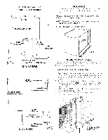 6
6 7
7 8
8