Fujitsu MAJ3364MP Manual/User Guide - Page 79
Cable connector requirements, Physical Interface Specifications.
 |
View all Fujitsu MAJ3364MP manuals
Add to My Manuals
Save this manual to your list of manuals |
Page 79 highlights
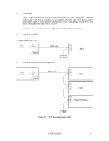
b. -WTP: Input signal (CN2-9, 10 pin) By connecting the CN2-10 pins to the GND, writing operations into the IDD disc media are set to disable. 4.3.3 Cable connector requirements Table 4.2 lists the recommended components cable connection. Table 4.2 Recommended components for connection Applicable model Name Par number MP SCSI cable (CN1) Cable socket 786090-7 (closed-end type) Signal cable - Power supply cable Cable socket (CN1) housing 1-480424-0 Contact 170121-4 Cable AWG20 External operator Cable socket panel (CN1) housing FCN-723J012/2M Contact FCN-723J-G/AM Cable AWG26 to 34 External operator Cable socket panel (CN2) housing FCN-723J016/2M Contact FCN-723J-G/AM Cable AWG28 MC SCSI connector Connector 787311-1 (CN1) Manufacturer AMP - AMP AMP Fujitsu Limited Fujitsu Limited Fujitsu Limited Fujitsu Limited AMP Reference (Figures 4.25 and 4.30) S1 S2 S3 S4 (1) SCSI cable See Section 1.3, "Physical Requirements", and Section 1.4, "Electrical Requirements", in SCSI Physical Interface Specifications. (2) Power cable IDDs must be star-connected to the DC power supply (one to one connection) to reduce the influence of load variations. (3) DC ground The DC ground cable must always be connected to the IDD because no fasten terminal dedicated to SG is provided with the IDD. Therefore, when SG and FG are connected in the system, it is necessary to connect SG and FG at the power supply or to connect SG of the power supply to FG of the system. 4 - 26 C141-E103-02EN
-
 1
1 -
2
-
3
-
4
-
5
-
6
-
7
-
8
-
9
-
10
-
11
-
12
-
13
-
14
-
15
-
16
-
17
-
18
-
19
-
20
-
21
-
22
-
23
-
24
-
25
-
26
-
27
-
28
-
29
-
30
-
31
-
32
-
33
-
34
-
35
-
36
-
37
-
38
-
39
-
40
-
41
-
42
-
43
-
44
-
45
-
46
-
47
-
48
-
49
-
50
-
51
-
52
-
53
-
54
-
55
-
56
-
57
-
58
-
59
-
60
-
61
-
62
-
63
-
64
-
65
-
66
-
67
-
68
-
69
-
70
-
71
-
72
-
73
-
 74
74 -
 75
75 -
 76
76 -
 77
77 -
 78
78 -
 79
79 -
 80
80 -
 81
81 -
 82
82 -
 83
83 -
 84
84 -
85
-
86
-
87
-
88
-
89
-
90
-
91
-
92
-
93
-
94
-
95
-
96
-
97
-
98
-
99
-
100
-
101
-
102
-
103
-
104
-
105
-
106
-
107
-
108
-
109
-
110
-
111
-
112
-
113
-
114
-
115
-
116
-
117
-
118
-
119
-
120
-
121
-
122
-
123
-
124
-
125
-
126
-
127
-
128
-
129
-
130
-
131
-
132
-
133
-
134
-
135
-
136
-
137
-
138
-
139
-
140
-
141
-
142
-
143
-
144
-
145
-
146
-
147
-
148
-
149
-
150
-
151
-
152
-
153
-
154
-
155
-
156
 |
 |
