Fujitsu MAJ3364MP Manual/User Guide - Page 80
External operator panel, 22 and pins 01 through 08 in CN2 and pins A1 through A12 in CN1.
 |
View all Fujitsu MAJ3364MP manuals
Add to My Manuals
Save this manual to your list of manuals |
Page 80 highlights
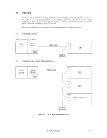
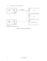
(4) External operator panel The external operator panel is installed only when required for the system. When connection is not required, leave open the following pins in the external operator panel connector of the IDD : Pins 21, 22 and pins 01 through 08 in CN2 and pins A1 through A12 in CN1. 4.3.4 External operator panel A recommended circuit of the external operator panel is shown in Figure 4.28. Since the external operator panel is not provided as an option, this panel must be fabricated at the user site referring to the recommendation if necessary. (MP) Figure 4.28 External operator panel circuit example IMPORTANT Do not connect the external LED to both CN1 and CN2. Connect it to either of them. C141-E103-02EN 4 - 27
-
 1
1 -
2
-
3
-
4
-
5
-
6
-
7
-
8
-
9
-
10
-
11
-
12
-
13
-
14
-
15
-
16
-
17
-
18
-
19
-
20
-
21
-
22
-
23
-
24
-
25
-
26
-
27
-
28
-
29
-
30
-
31
-
32
-
33
-
34
-
35
-
36
-
37
-
38
-
39
-
40
-
41
-
42
-
43
-
44
-
45
-
46
-
47
-
48
-
49
-
50
-
51
-
52
-
53
-
54
-
55
-
56
-
57
-
58
-
59
-
60
-
61
-
62
-
63
-
64
-
65
-
66
-
67
-
68
-
69
-
70
-
71
-
72
-
73
-
74
-
 75
75 -
 76
76 -
 77
77 -
 78
78 -
 79
79 -
 80
80 -
 81
81 -
 82
82 -
 83
83 -
 84
84 -
 85
85 -
86
-
87
-
88
-
89
-
90
-
91
-
92
-
93
-
94
-
95
-
96
-
97
-
98
-
99
-
100
-
101
-
102
-
103
-
104
-
105
-
106
-
107
-
108
-
109
-
110
-
111
-
112
-
113
-
114
-
115
-
116
-
117
-
118
-
119
-
120
-
121
-
122
-
123
-
124
-
125
-
126
-
127
-
128
-
129
-
130
-
131
-
132
-
133
-
134
-
135
-
136
-
137
-
138
-
139
-
140
-
141
-
142
-
143
-
144
-
145
-
146
-
147
-
148
-
149
-
150
-
151
-
152
-
153
-
154
-
155
-
156
 |
 |

C141-E103-02EN
4 - 27
(4)
External operator panel
The external operator panel is installed only when required for the system.
When connection is not
required, leave open the following pins in the external operator panel connector of the IDD :
Pins
21, 22 and pins 01 through 08 in CN2 and pins A1 through A12 in CN1.
4.3.4
External operator panel
A recommended circuit of the external operator panel is shown in Figure 4.28.
Since the external
operator panel is not provided as an option, this panel must be fabricated at the user site referring
to the recommendation if necessary.
(MP)
Figure 4.28
External operator panel circuit example
IMPORTANT
Do not connect the external LED to both CN1 and CN2.
Connect it
to either of them.