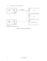
Fujitsu MAJ3364MP Manual/User Guide - Page 87
SCSI ID setting, Force Single Ended
 |
View all Fujitsu MAJ3364MP manuals
Add to My Manuals
Save this manual to your list of manuals |
Page 87 highlights
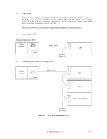
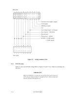
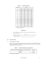
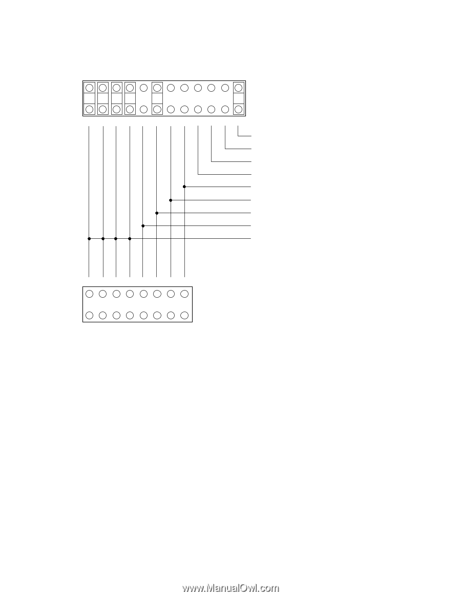
MP model 2 4 6 8 10 12 14 16 18 20 22 24 1 3 5 7 9 11 13 15 17 19 21 23 Terminal power supply: Supply (LED signal) (IDD Reset signal) N.C. Force Single Ended: LVD mode Force Narrow: 16bit-SCSI Spin-up mode Write protect: enabled SCSI ID #15 (MP model) # 0 (MC model) 2 4 6 8 10 12 14 16 1 3 5 7 9 11 13 15 MC model Figure 5.3 Setting terminals (CN2) 5.3.1 SCSI ID setting Table 5.1 shows the SCSI ID setting. Refer to Figures 5.2 and 5.3 for connector positioning and allocation. IMPORTANT When the SCSI ID is set using the external operator panel connector CN1, all pins listed in Table 5.1 should be open. If any of pins are shorted, unexpected SCSI ID is set. 5 - 6 C141-E103-02EN
-
 1
1 -
2
-
3
-
4
-
5
-
6
-
7
-
8
-
9
-
10
-
11
-
12
-
13
-
14
-
15
-
16
-
17
-
18
-
19
-
20
-
21
-
22
-
23
-
24
-
25
-
26
-
27
-
28
-
29
-
30
-
31
-
32
-
33
-
34
-
35
-
36
-
37
-
38
-
39
-
40
-
41
-
42
-
43
-
44
-
45
-
46
-
47
-
48
-
49
-
50
-
51
-
52
-
53
-
54
-
55
-
56
-
57
-
58
-
59
-
60
-
61
-
62
-
63
-
64
-
65
-
66
-
67
-
68
-
69
-
70
-
71
-
72
-
73
-
74
-
75
-
76
-
77
-
78
-
79
-
80
-
81
-
 82
82 -
 83
83 -
 84
84 -
 85
85 -
 86
86 -
 87
87 -
 88
88 -
 89
89 -
 90
90 -
 91
91 -
 92
92 -
93
-
94
-
95
-
96
-
97
-
98
-
99
-
100
-
101
-
102
-
103
-
104
-
105
-
106
-
107
-
108
-
109
-
110
-
111
-
112
-
113
-
114
-
115
-
116
-
117
-
118
-
119
-
120
-
121
-
122
-
123
-
124
-
125
-
126
-
127
-
128
-
129
-
130
-
131
-
132
-
133
-
134
-
135
-
136
-
137
-
138
-
139
-
140
-
141
-
142
-
143
-
144
-
145
-
146
-
147
-
148
-
149
-
150
-
151
-
152
-
153
-
154
-
155
-
156
 |
 |
C141-E103-02EN
5 - 6
24
22
20
18
16
14
12
10
8
6
MC model
MP model
4
2
23
21
19
17
15
13
11
9
7
5
3
1
Terminal power supply:
Supply
(LED signal)
(IDD Reset signal)
N.C.
Force Single Ended:
LVD mode
Force Narrow:
16bit-SCSI
Spin-up mode
Write protect:
enabled
SCSI ID
#15 (MP model)
#
0 (MC model)
16
14
12
10
8
6
4
2
15
13
11
9
7
5
3
1
Figure 5.3
Setting terminals (CN2)
5.3.1
SCSI ID setting
Table 5.1 shows the SCSI ID setting. Refer to Figures 5.2 and 5.3 for connector positioning and
allocation.
IMPORTANT
When the SCSI ID is set using the external operator panel connector
CN1, all pins listed in Table 5.1 should be open.
If any of pins are
shorted, unexpected SCSI ID is set.