GE AZ41E12DAB Owners Manual - Page 14
Installation Instructions, VOLT ELECTRICAL CONNECTION OPTIONS
 |
View all GE AZ41E12DAB manuals
Add to My Manuals
Save this manual to your list of manuals |
Page 14 highlights
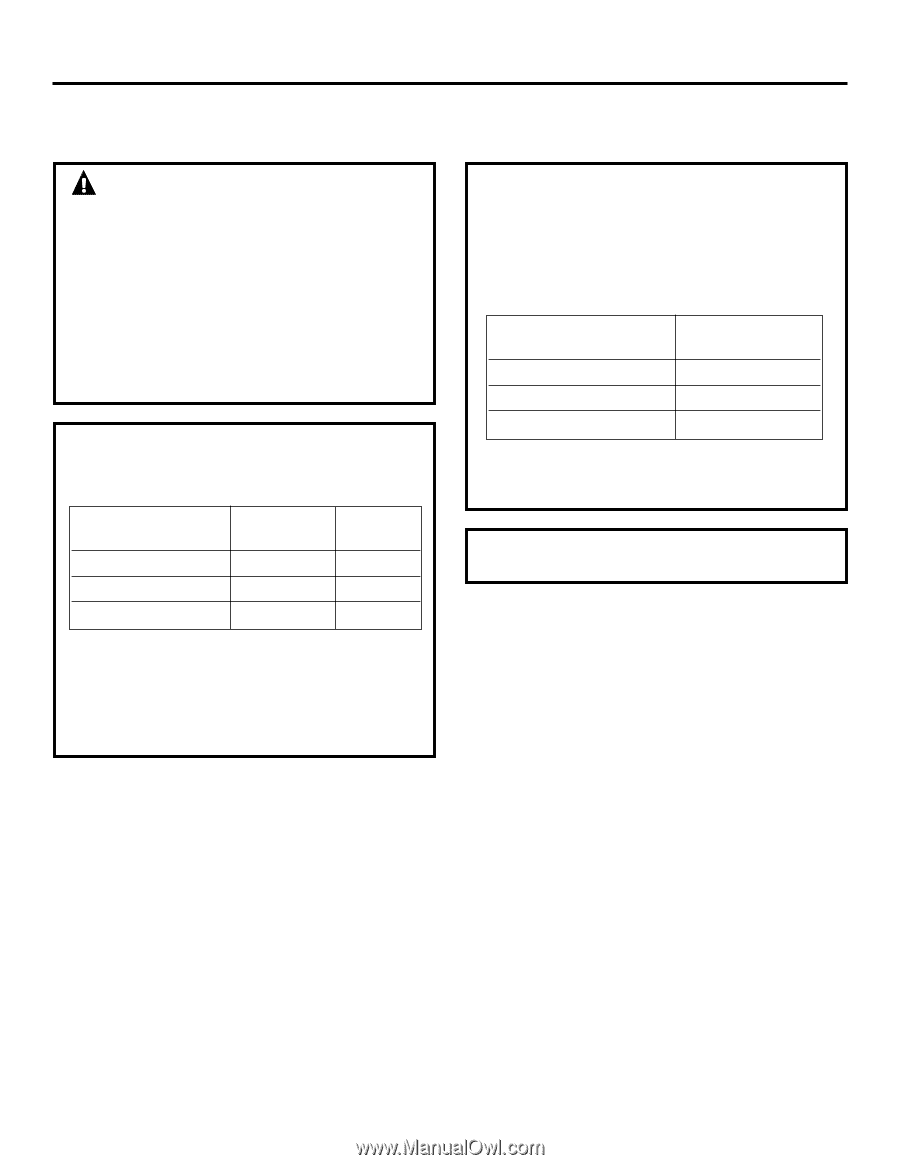
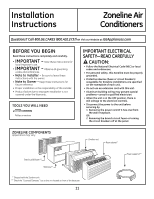
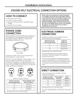
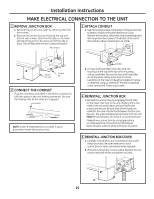
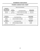
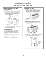
Installation Instructions 265 VOLT ELECTRICAL CONNECTION OPTIONS WARNINg: Connection of this 265 V AC product to a branch circuit MUST be done by direct connection in accordance with the National Electrical Code. Plugging this unit into a building-mounted exposed receptacle is not permitted by code. These models must be installed using the appropriate GE power supply kit for the branch circuit amperage and the electrical resistance heater wattage desired. Use the POWER CONNECTION CHART on page 16 to determine the correct kit required. One of the following installation methods (A or B) must be used. A. FOR SuBBASE INSTALLATION Electrical subbase kits are available to provide a flexible enclosure for direct connection. Branch Circuit and Unit Amperage Rating 15 20 30 Proper GE Subbase Kit RAK204E15 RAK204E20 RAK204E30 Power Supply Kit RAK5172 RAK5202 RAK5302* *Not approved for use on 7000 BTU models. The instructions provided with the selected subbase kit must be carefully followed. It is the responsibility of the installer to ensure the connection of components is done in accordance with these instructions and all electrical codes. B. FOR DIRECT CONNECT INSTALLATION If an electrical subbase is not used, direct connection to branch circuit wiring inside the provided junction box must be done in accordance with the following steps. Order the following Kit for 265-volt direct connection as required: Branch Circuit and Unit Amperage Rating Power Supply Kit 15 RAK5157 20 RAK5207 30 RAK5307* *Not approved for use on 7000 BTU models. Proceed to the "MAKE ELECTRICAL CONNECTION TO THE UNIT" section. NOTE: Order Kit RAK4002CW to enable a quick disconnect inside the junction box. 14
-
 1
1 -
2
-
3
-
4
-
5
-
6
-
7
-
8
-
 9
9 -
 10
10 -
 11
11 -
 12
12 -
 13
13 -
 14
14 -
 15
15 -
 16
16 -
 17
17 -
 18
18 -
 19
19 -
20
-
21
-
22
-
23
-
24
-
25
-
26
-
27
-
28
-
29
-
30
-
31
-
32
-
33
-
34
-
35
-
36
-
37
-
38
-
39
-
40
-
41
-
42
-
43
-
44
-
45
-
46
-
47
-
48
-
49
-
50
-
51
-
52
-
53
-
54
-
55
-
56
-
57
-
58
-
59
-
60
-
61
-
62
-
63
-
64
-
65
-
66
-
67
-
68
-
69
-
70
-
71
-
72
 |
 |