GE AZ41E12DAB Owners Manual - Page 16
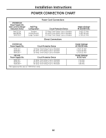
Installation Instructions, POWER CONNECTION CHART
 |
View all GE AZ41E12DAB manuals
Add to My Manuals
Save this manual to your list of manuals |
Page 16 highlights
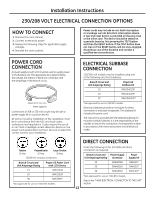
Installation Instructions POWER CONNECTION CHART 230/208 Volt Power Supply Kits with Current Leakage Detection Device RAK3153A RAK3203A RAK3303* Power Cord Connections Wall Plug Configuration Tandem Perpendicular Large Tandem Circuit Protective Device 15-Amp Time-Delay Fuse or Breaker 20-Amp Time-Delay Fuse or Breaker 30-Amp Time-Delay Fuse or Breaker Direct Connections Heater Wattage @ 230/208 Volts 2.40/2.32 KW 3.30/3.20 KW 4.70/4.53 KW 230/208 Volt Power Supply Kits Circuit Protective Device RAK4157 RAK4207 RAK4307* 15-Amp Time-Delay Fuse or Breaker 20-Amp Time-Delay Fuse or Breaker 30-Amp Time-Delay Fuse or Breaker 265 Volt Power Supply Kits Circuit Protective Device RAK5157 RAK5207 RAK5307* 15-Amp Time-Delay Fuse or Breaker 20-Amp Time-Delay Fuse or Breaker 30-Amp Time-Delay Fuse or Breaker *Not approved for use on 7000 BTUH units. Heater Wattage @ 230/208 Volts 2.40/2.32 KW 3.30/3.20 KW 4.70/4.53 KW Heater Wattage @ 265 Volts 2.40 KW 3.40 KW 4.80 KW 16
-
 1
1 -
2
-
3
-
4
-
5
-
6
-
7
-
8
-
9
-
10
-
 11
11 -
 12
12 -
 13
13 -
 14
14 -
 15
15 -
 16
16 -
 17
17 -
 18
18 -
 19
19 -
 20
20 -
 21
21 -
22
-
23
-
24
-
25
-
26
-
27
-
28
-
29
-
30
-
31
-
32
-
33
-
34
-
35
-
36
-
37
-
38
-
39
-
40
-
41
-
42
-
43
-
44
-
45
-
46
-
47
-
48
-
49
-
50
-
51
-
52
-
53
-
54
-
55
-
56
-
57
-
58
-
59
-
60
-
61
-
62
-
63
-
64
-
65
-
66
-
67
-
68
-
69
-
70
-
71
-
72
 |
 |
