GE AZ41E12DAB Owners Manual - Page 15
Installation Instructions, MAKE ELECTRICAL CONNECTION TO THE UNIT
 |
View all GE AZ41E12DAB manuals
Add to My Manuals
Save this manual to your list of manuals |
Page 15 highlights
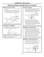
Installation Instructions MAKE ELECTRICAL CONNECTION TO THE uNIT 1 REMOVE JuNCTION BOX 1. Remove the junction box cover by removing the front two screws. 2. Remove the junction box by removing the top and bottom rear screws. Note how the tabs on the lower left side of the junction box serve to hold the side in place. This will help when the box is being reinstalled. Unit connector 3 ATTACH CONDuIT 1. Use the round knockout at the bottom of the junction box to attach conduit coming from the branch circuit. Remove the knockout, attach the conduit and bring wires into the junction box. Leave 6" of wire free at the end of the conduit to allow connections to be made. Junction box cover Junction box 2 CONNECT THE CORDSET Plug the connector, provided in the Direct Connect Kit, fully into place in the unit mating connector. Be sure the locking tabs at the sides are engaged. Connector NOTE: Order Kit RAK4002CW to enable a quick disconnect inside the junction box. Conduit 2. If a fuse and fuseholder are to be used, the knockout at the top of the box is for mounting a Buss fuseholder. Be sure the fuse and fuseholder are of the same rating as the branch circuit. Leadwires at the fuse can be either soldered in place or attached using UL-listed 1/4" female (receptacle) crimp connectors. Follow local codes. 4 REINSTALL JuNCTION BOX • Reinstall the junction box by engaging the left tabs on the lower right face of the unit, aligning the screw holes at the top and bottom and driving the two screws until secure. Be sure that all wire leads are inside the box and not pinched between the box and the unit. The green insulated ground wire from the unit MUST be connected to the branch circuit ground wire. Make all wire connections by using appropriate UL-listed electrical connectors and techniques (black to black, white to white and green to green). 5 REINSTALL JuNCTION BOX COVER 1. Carefully tuck all wires and connections back inside the junction box. Be sure there are no loose connections or stray uninsulated wires exposed. 2. Place the junction box cover in place. Replace the two screws removed earlier and tighten securely. 15
-
 1
1 -
2
-
3
-
4
-
5
-
6
-
7
-
8
-
9
-
 10
10 -
 11
11 -
 12
12 -
 13
13 -
 14
14 -
 15
15 -
 16
16 -
 17
17 -
 18
18 -
 19
19 -
 20
20 -
21
-
22
-
23
-
24
-
25
-
26
-
27
-
28
-
29
-
30
-
31
-
32
-
33
-
34
-
35
-
36
-
37
-
38
-
39
-
40
-
41
-
42
-
43
-
44
-
45
-
46
-
47
-
48
-
49
-
50
-
51
-
52
-
53
-
54
-
55
-
56
-
57
-
58
-
59
-
60
-
61
-
62
-
63
-
64
-
65
-
66
-
67
-
68
-
69
-
70
-
71
-
72
 |
 |
