Genie ProMax Stealth Owner's Manual - Page 17
d_39905_38124_14.0
 |
View all Genie ProMax Stealth manuals
Add to My Manuals
Save this manual to your list of manuals |
Page 17 highlights
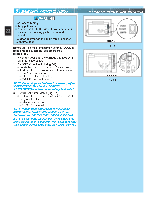
OPEN YELLOW PARTS BAG Str CAUTION ket m ge [91] Bolt, 3/8-16 x 7/8" fr Do Not fasten to drywall, particle board, Cur 9. Mount po TERNATE [92] 3/8-16 nut 17 MOUNTING METHODS). • Be sure rail assembly and power head are on door center line (line "V"). • Check the illustrations. Decide which mounting Fig. 2-16 method you will use. Materials for mounting are not included. • After power head is installed, remove supporting material. • Close door. 10. xactly as shown (Fig. 2-16). Clevis pin[[8990]] • Overlap arms by two (2) holes. • Install two (2) 3/8" x 7/8" hex bolts, and hex flange nuts. • Tighten hex nuts securely. 11. Install assemb 2-17). Fig. 2-17 • Attach straight end of assembled door arms to door bracket. - slip straight door arm into slot in door bracket. - secure with clevis pin [90] and cotter pin [89]. • Release carriage (See emergency release tag). • Slide carriage toward door. • Attach short end of curved door arm to carriage. - slip curved door arm into slot in carriage. - secure with clevis pin and cotter pin. [92] [91] Nut, 3/8-16 Bolt, 3/8"-16 x 7/8" Npcrc1eo.aoO8qlms0lTuii0ntpEiir.gol3:een5Wdtthi4.noeh.A3greC6ninpf4urey3osex.optvtoueeiomnnausiernsierogsSnn,teodekrtopivtoa;iccbraaelmelnoputnbhosgeotcennplroeoudstrnoecpuohatmrhasseabseredmldreo,vboiseyrlafter 12. Adjust emergenc d length. • Mount the emergency release knob 6 feet from the floor. • Retie overhand knot and trim excess cord. [90]Clevis pin d_39905_38124_14.0 [89]Cotter pin
-
 1
1 -
2
-
3
-
4
-
5
-
6
-
7
-
8
-
9
-
10
-
11
-
 12
12 -
 13
13 -
 14
14 -
 15
15 -
 16
16 -
 17
17 -
 18
18 -
 19
19 -
 20
20 -
 21
21 -
 22
22 -
23
-
24
-
25
-
26
-
27
-
28
-
29
-
30
-
31
-
32
 |
 |
