Genie ProMax Stealth Owner's Manual - Page 20
Dealer. Only One Of Your Wall Controls May
 |
View all Genie ProMax Stealth manuals
Add to My Manuals
Save this manual to your list of manuals |
Page 20 highlights
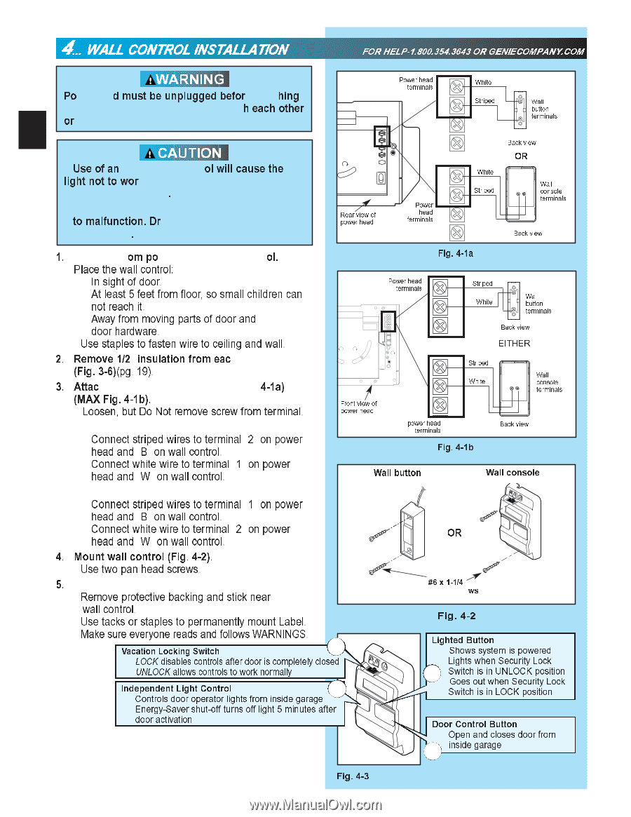
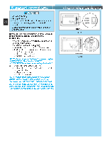
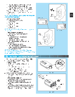
4... WALL CONTROL INSTALLATION FOR HELP-1.800.354.3643 OR GENIECOMPANY.COM Po 20 or WARNING d must be unplugged befor hing h each other CAUTION •ligUhstenooft atonwor ol will cause the . • to malfunction. Dr . 1. om po ol. • Place the wall control: - In sight of door. - At least 5 feet from floor, so small children can not reach it. - Away from moving parts of door and door hardware. • Use staples to fasten wire to ceiling and wall. 2. (RFeigm.o3v-6e)(1p/2g". insulation 19). from eac 3. Attac 4-1a) (MAX Fig. 4-1b). • Loosen, but Do Not remove screw from tLeOrminal. - Connect striped wires to terminal "2" on power head and "B" on wall control. - Connect white wire to terminal "1" Lon power head and "W" on wall control. MORE OPEN MENT W1 2 Y3 G4 PUSH TO SET L MITS Rpoewaer rviheewadof Power head terminals 1 2 3 4 White Striped 1 2 Power fermhineaalds 3 4 White Striped Fig. 4-1a Wall W button B terminals Back view OR Wall BW console terminals Back view Power head terminals NEC E: CO ONL W NO E UE NY S SER E CON ROLS BE DO N T USH LMTS UN E S D OR I ATCE CLOSE MORE OPEN MORE SE OPEN IMIT ADJUSTMENT U S Patent o 5 243 784 5 21 869 LIM T SET OPEN FOR E CLO E FOR E RAD O SIG AL LEA N CODE 1 2 3 4 5 6 MORE FORCE Striped 1 2 White W Wall B button terminals 3 Back view EITHER 1 Striped 2 White Wall BW console terminals FporownSeEtrURvSIhiEeEeSwOaIINdoCfY 3 power head teNOrTminals Back view Fig.54-1b Wall butCLtOIoDMEInT Wall console - Connect striped wires to terminal "1" MoOn Epower head and "B" on wall control. - Connect white wire to terminal "2" on power head and "W" on wall control. 4. Mount wall control (Fig. 4-2). • Use two pan head screws. 5. • Remove protective backing and stick near wall control. • Use tacks or staples to permanently mount Label. • Make sure everyone reads and follows WARNINGS. Vacation Locking Switch 1 - LOCK disables controls after door is completely closed - UNLOCK allows controls to work normally Independent Light Control - Controls door operator lights from inside garage 4 - Energy-Saver shut-off turns off light 5 minutes after door activation NOTE: Additional wall controls are available from your dealer. ONLY ONE OF YOUR WALL CONTROLS MAY BE THE LIGHTED TYPE. If you have a lighted wall control, all your additional controls must be un-lighted. More than one lighted wall control per operator will cause a malfunction. Fig. 4-3 OR #6 x 1-1/4" ws Fig. 4-2 Lighted Button - Shows system is powered - Lights when Security Lock 2 Switch is in UNLOCK position - Goes out when Security Lock Switch is in LOCK position Door Control Button - Open and closes door from 3 inside garage
-
 1
1 -
2
-
3
-
4
-
5
-
6
-
7
-
8
-
9
-
10
-
11
-
12
-
13
-
14
-
 15
15 -
 16
16 -
 17
17 -
 18
18 -
 19
19 -
 20
20 -
 21
21 -
 22
22 -
 23
23 -
 24
24 -
 25
25 -
26
-
27
-
28
-
29
-
30
-
31
-
32
 |
 |