Genie ScrewDrive Owner's Manual - Page 13
Fig. 1-13, Fig. 1-14, engaged, released, arrow, Fig. 1-15, power, carriage stop, carriage, Fig. 1-16
 |
View all Genie ScrewDrive manuals
Add to My Manuals
Save this manual to your list of manuals |
Page 13 highlights
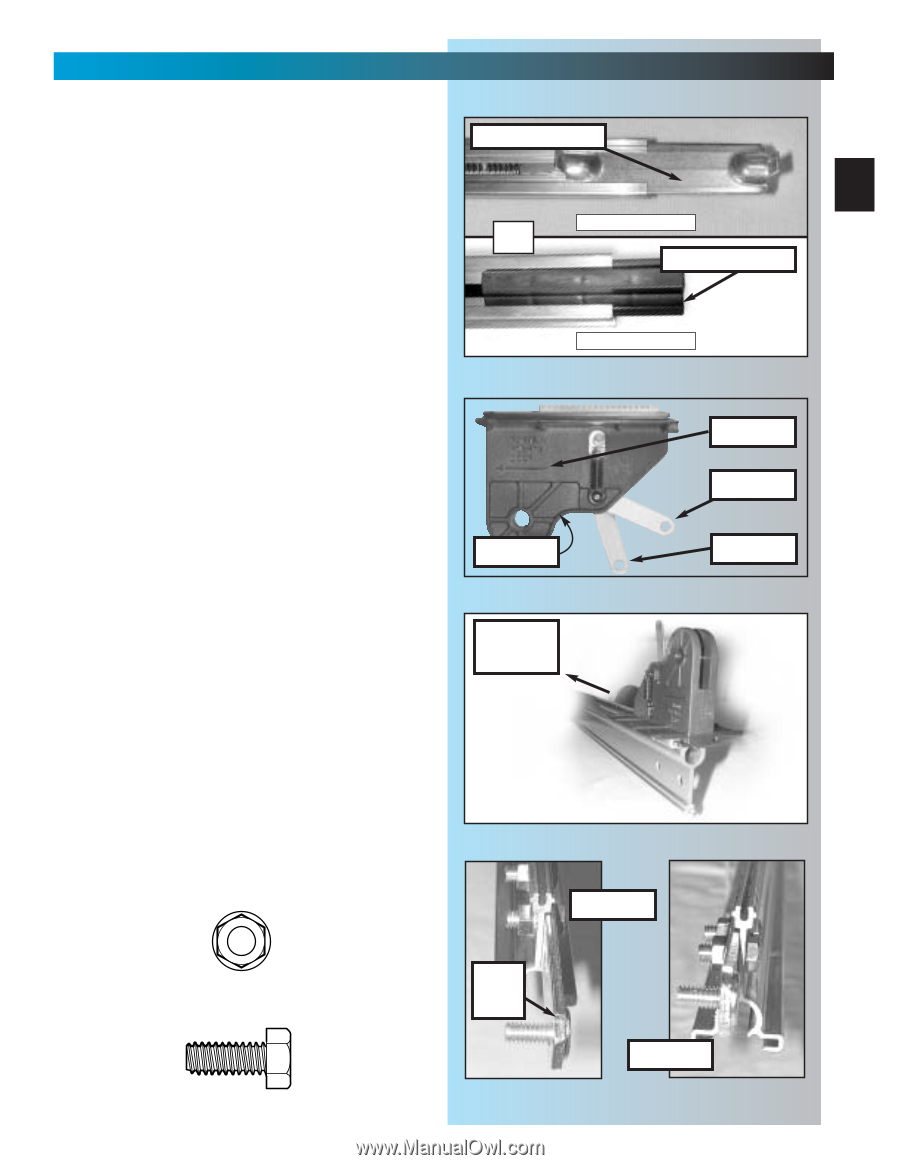
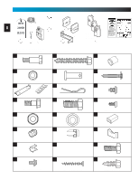
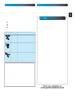
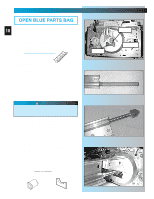
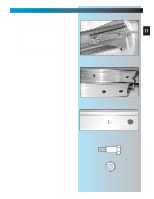
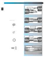
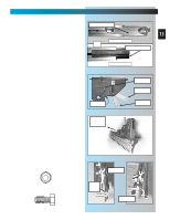
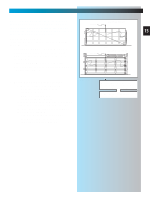
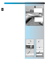
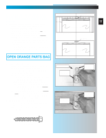
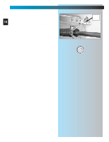
MAIN ASSEMBLY FOR HELP-1.800.354.3643 OR GENIECOMPANY.COM NOTE: If installing an extension kit for an 8 feet high door, refer to the instructions carriage stop included with the extension kit now. 7. Attach "end" rail section [3C]. 13 • Attach "end" rail in same way as "middle" rail (step 5). ("End" rail section screw has "hook" on one end only.) 8. Flip power head/rail assembly over (upside OR USES BUMPER carriage stop down), so that entire length of screw is visible from above. 9. Install carriage stop [6]. • With bent tabs facing up, slide carriage stop into rail. Fig. 1-13. • Slide carriage stop along rail until it rests against power head. Fig. 1-13 NO BUMPER 10. Install carriage [10]. • Place emergency release lever in released position. Fig. 1-14. • Make sure arrow on side of carriage (Fig. 1-14) is pointing away from power head. (Emergency release lever will be facing power head.) • Slide carriage into rail. Fig. 1-15. carriage arrow engaged released NOTE: Carriage can be used as a temporary support for the rail while performing the next few steps of assembly. Slide carriage to mid point of rail. Place emergency release lever in engaged position. Fig. 1-14 power head 11. Flip assembly right side up. (Rail resting on carriage.) 12. Attach rail strap [13]. • Place rail strap against end of rail so that attached stud passes in front of end of rail. Fig. 1-16. • Line up rail strap holes with rail holes. • Secure with 2 bolts [46] and 2 nuts [9]. 13. Make sure rail assembly is resting straight and level. • FULLY TIGHTEN ALL BOLTS AND NUTS IN RAIL ASSEMBLY. Fig. 1-15 correct [9] 5/16" Flange nut rail strap [46] 5/16" x 3/4" Hex head bolt Fig. 1-16 wrong
-
 1
1 -
2
-
3
-
4
-
5
-
6
-
7
-
 8
8 -
 9
9 -
 10
10 -
 11
11 -
 12
12 -
 13
13 -
 14
14 -
 15
15 -
 16
16 -
 17
17 -
 18
18 -
19
-
20
-
21
-
22
-
23
-
24
-
25
-
26
-
27
-
28
-
29
-
30
-
31
-
32
-
33
-
34
-
35
 |
 |