Genie ScrewDrive Owner's Manual - Page 22
Open Red Parts Bag - garage door parts
 |
View all Genie ScrewDrive manuals
Add to My Manuals
Save this manual to your list of manuals |
Page 22 highlights
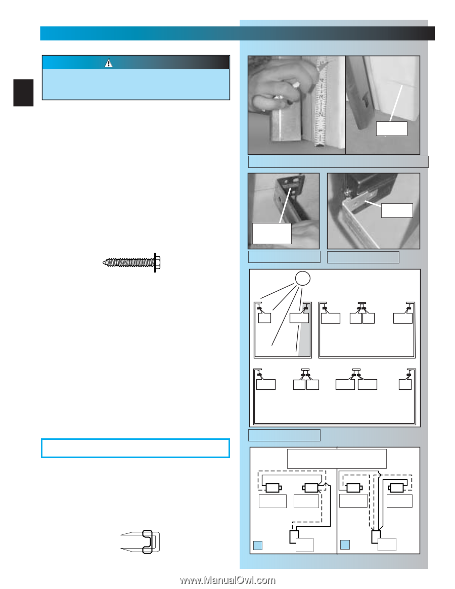
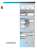
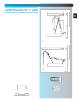
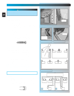
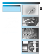
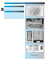
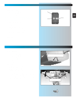
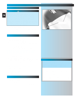
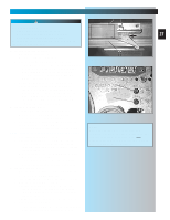
SECT 3-SAFE-T-BEAM ® INSTALLATION FOR HELP-1.800.354.3643 WARNING There should be no electrical power to the operator while installing Safe-T-Beam System® wires. If you 22 have plugged in the power cord-UNPLUG IT NOW. NOTE: Operator will not close door automatically unless the Safe-T-Beam® System is installed. 1. Mounting brackets. • Mark both sides of garage door frame or wall 5" above floor. Fig. 3-1. • Hold bracket [38] against door frame or wall. - Check if brackets extend out from wall far enough, so tongue of bracket is beyond door, tracks or any door hardware. - If not: a. STB bracket extensions are available at local dealer. b. Blocks of wood, etc. may be substituted for extensions. • Center bracket on your mark Fig. 3-2. • Fasten each with 2 screws [40]. Fig. 3-2. (Tongues should point toward each other.) [40] #10-16 x 1-1/4" NOTE: Mounting brackets can be attached to brick walls or concrete floor using masonry anchors (not provided). 2. Mounting STB source and sensor. • If garage has only one garage door. - Determine which side of garage receives most direct sunlight Fig. 3-4, and place Red LED here whenever possible Fig. 3-4. • For multiple doors. - Preventing crossed signals is critical. - Place source and sensor modules on adjacent doors facing in opposite directions Fig. 3-4. NOTE:To help prevent interference from sun, STB sensors (Green LED) may be placed further from the door opening where they will spend more time in shadows. • Slide source/sensor onto tongue of bracket until it clicks into place Fig. 3-3. OPEN RED PARTS BAG 3. Wiring. • Route wire [29] using either method shown Fig. 3-5. • Securely fasten wires to ceiling and walls as you go using insulated staples [30]. - Staples should be snug only. Staples which are too tight can cut wires. [30] Insulated staple Fig. 3-1 mark center of bracket Fig. 3-2 SUN Fig. 3-3 tongue RED LED GREEN LED GREEN LED RED RED LED LED GREEN LED ONE DOOR GARAGE TWO DOOR GARAGE GREEN LED RED RED LED LED GREEN GREEN LED LED RED LED THREE DOOR GARAGE Fig. 3-4 Dashed Line = striped wire Solid Line = white wire Source Red LED Sensor Green LED Source Red LED Sensor Green LED A Power Head B Power Head Fig. 3-5
-
 1
1 -
2
-
3
-
4
-
5
-
6
-
7
-
8
-
9
-
10
-
11
-
12
-
13
-
14
-
15
-
16
-
 17
17 -
 18
18 -
 19
19 -
 20
20 -
 21
21 -
 22
22 -
 23
23 -
 24
24 -
 25
25 -
 26
26 -
 27
27 -
28
-
29
-
30
-
31
-
32
-
33
-
34
-
35
 |
 |