Genie ScrewDrive Owner's Manual - Page 6
Piece Rail Hardware Exploded View, Parts List
 |
View all Genie ScrewDrive manuals
Add to My Manuals
Save this manual to your list of manuals |
Page 6 highlights
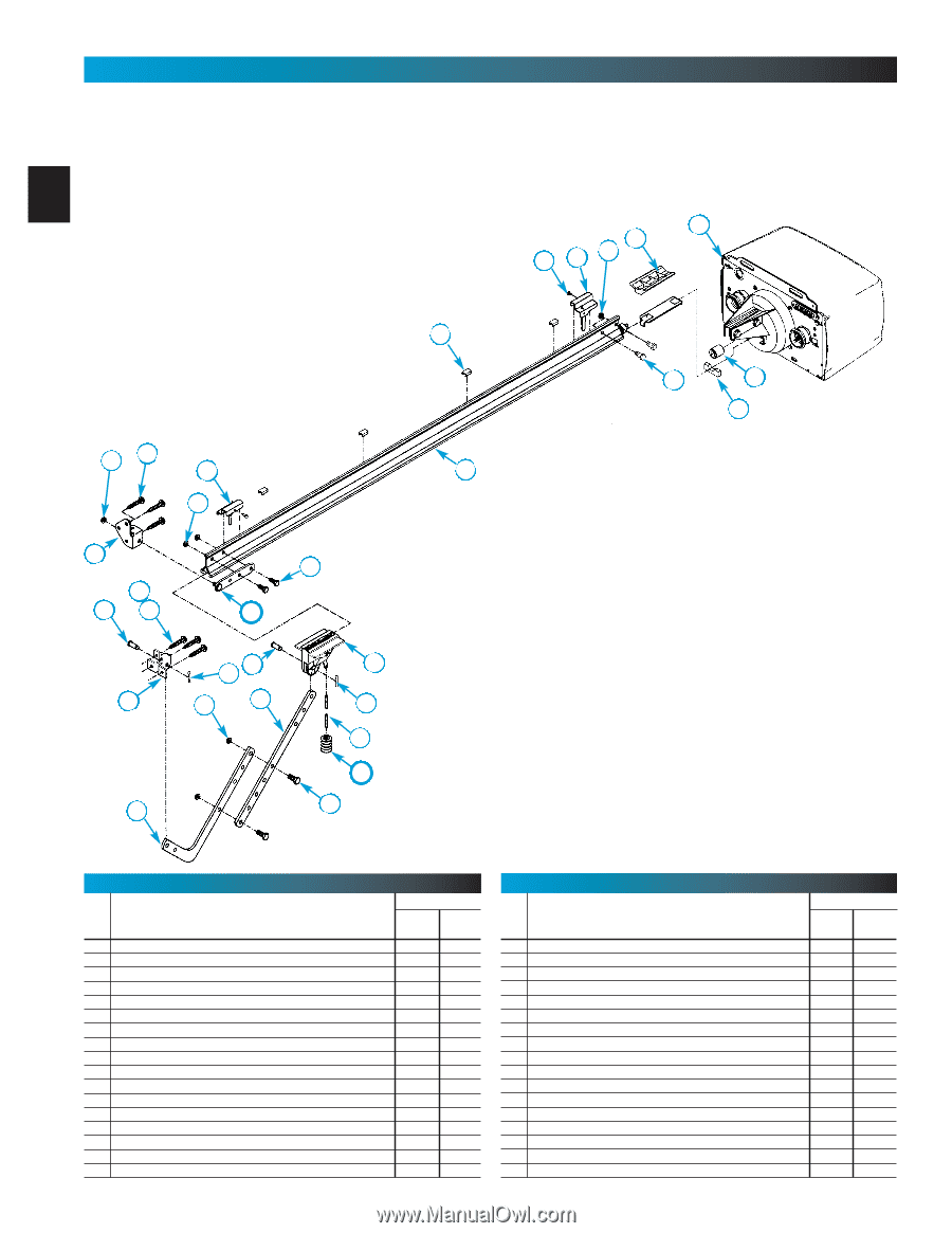
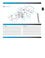
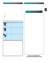
1-PIECE RAIL HARDWARE EXPLODED VIEW [2] 1-Piece Rail & Screw Assembly FOR HELP-1.800.354.3643 OR GENIECOMPANY.COM NOTE: The operator will not function properly unless the Safe-T-Beam® 6 sensors are installed and the force controls adjusted. 1 6 16 15A 5 OR 9 22 15B 9 44 2 4 39 45 20 47 24 22 46 13 25 24 10 21 28 23 25 17 18 26 27 PARTS LIST Item Part Name 1 Power Head Assembly (See page 5) 2 Rail Assembly (1 piece) 3 Rail Assembly (3 piece) 3A First Rail Section 3B Middle Rail Section 3C End Rail Section 4 1/4-20 Hex Hd Shoulder Bolt 5 1/4"-20 Hex Flange Nut 6 Carriage Stop 7 Rail Clamps 8 5/16" Hex Shoulder Bolt 9 5/16" Hex Flange Nut 10 Carriage Assembly 11 Collar 12 Retaining Clip 13 Rail Strap 15A Open Limit Switch Assembly (Grey) Parts Required 1 Piece 3-Piece 1 1 1 1 1 1 1 2 2 2 2 1 1 4 8 5 13 1 1 2 2 1 1 1 1 PARTS LIST Item Part Name 15B Close Limit Switch Assembly (Brown) 16 No. 8-32 x 3/8" Hex Head Screw 17 Emergency Release Cord 18 Emergency Release Knob 19 Emergency Release Tag 20 Header Bracket 21 Door Bracket 22 1/4" x 2" Lag Screw 23 Straight Door Arm 24 Clevis Pin 25 Cotter Pin 26 Curved Door Arm 27 3/8" x 7/8" Hex Head Bolt 28 3/8" Hex Flange Nut 29 Wire 30 Insulated Staple 31 Wall Button Parts Required 1 Piece 3-Piece 1 1 2 2 1 1 1 1 1 1 1 1 1 1 8 8 1 1 2 2 2 2 1 1 2 2 2 2 ~~95ft ~~95ft ~~ 30 ~~ 30 varies varies
-
 1
1 -
 2
2 -
 3
3 -
 4
4 -
 5
5 -
 6
6 -
 7
7 -
 8
8 -
 9
9 -
 10
10 -
 11
11 -
 12
12 -
13
-
14
-
15
-
16
-
17
-
18
-
19
-
20
-
21
-
22
-
23
-
24
-
25
-
26
-
27
-
28
-
29
-
30
-
31
-
32
-
33
-
34
-
35
 |
 |