Gigabyte GA-VM800PMC Manual - Page 22
F_AUDIO Front Audio Panel Connector, PWR_LED - buy
 |
View all Gigabyte GA-VM800PMC manuals
Add to My Manuals
Save this manual to your list of manuals |
Page 22 highlights
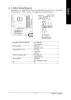
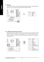
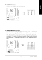
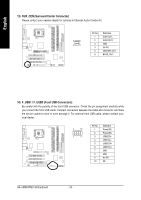
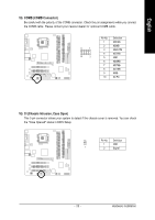
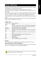
English 9) PWR_LED The PWR_LED connector is connected with the system power indicator to indicate whether the system is on/off. It will blink when the system enters suspend mode(S1). Pin No. Definition 1 MPD+ 1 2 MPD- 3 MPD- 10) F_AUDIO (Front Audio Panel Connector) Please make sure the pin assignment on the cable is the same as the pin assigment on the MB header. To find out if the chassis you are buying support front audio panel connector, please contact your dealer. If you want to use "Front Audio" connector, you must remove the jumpers from pins 5-6, 9-10. 10 9 2 1 Pin No. 1 2 3 4 5 6 7 8 9 10 Definition MIC GND MIC_BIAS POWER FrontAudio(R) Rear Audio (R)/ Return R NC No Pin FrontAudio (L) Rear Audio (L)/ Return L GA-VM800PMC Motherboard - 22 -
-
 1
1 -
2
-
3
-
4
-
5
-
6
-
7
-
8
-
9
-
10
-
11
-
12
-
13
-
14
-
15
-
16
-
 17
17 -
 18
18 -
 19
19 -
 20
20 -
 21
21 -
 22
22 -
 23
23 -
 24
24 -
 25
25 -
 26
26 -
 27
27 -
28
-
29
-
30
-
31
-
32
-
33
-
34
-
35
-
36
-
37
-
38
-
39
-
40
-
41
-
42
-
43
-
44
-
45
-
46
-
47
-
48
-
49
-
50
-
51
-
52
-
53
-
54
-
55
-
56
-
57
-
58
-
59
-
60
-
61
-
62
-
63
-
64
-
65
-
66
-
67
-
68
-
69
-
70
-
71
-
72
-
73
-
74
-
75
-
76
-
77
-
78
-
79
-
80
-
81
-
82
-
83
-
84
-
85
-
86
-
87
-
88
 |
 |
