Gigabyte GA-VM800PMC Manual - Page 24
SUR_CEN Surround Center Connector, F_USB1 / F_USB2 Front USB Connectors
 |
View all Gigabyte GA-VM800PMC manuals
Add to My Manuals
Save this manual to your list of manuals |
Page 24 highlights
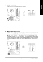
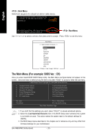
English 13) SUR_CEN (Surround Center Connector) Please contact your nearest dealer for optional 6-Channel Audio Combo Kit. 6 5 2 1 Pin No. 1 2 3 4 5 6 Definition SUR OUTL SUR OUTR GND No Pin CENTER_OUT BASS_OUT 14) F_USB1 / F_USB2 (Front USB Connectors) Be careful with the polarity of the front USB connector. Check the pin assignment carefully while you connect the front USB cable, incorrect connection between the cable and connector will make the device unable to work or even damage it. For optional front USB cable, please contact your local dealer. 2 10 1 9 Pin No. 1 2 3 4 5 6 7 8 9 10 Definition Power(5V) Power(5V) USB0 DXUSB1 DyUSB0 DX+ USB1 Dy+ GND GND No Pin NC GA-VM800PMC Motherboard - 24 -
-
 1
1 -
2
-
3
-
4
-
5
-
6
-
7
-
8
-
9
-
10
-
11
-
12
-
13
-
14
-
15
-
16
-
17
-
18
-
 19
19 -
 20
20 -
 21
21 -
 22
22 -
 23
23 -
 24
24 -
 25
25 -
 26
26 -
 27
27 -
 28
28 -
 29
29 -
30
-
31
-
32
-
33
-
34
-
35
-
36
-
37
-
38
-
39
-
40
-
41
-
42
-
43
-
44
-
45
-
46
-
47
-
48
-
49
-
50
-
51
-
52
-
53
-
54
-
55
-
56
-
57
-
58
-
59
-
60
-
61
-
62
-
63
-
64
-
65
-
66
-
67
-
68
-
69
-
70
-
71
-
72
-
73
-
74
-
75
-
76
-
77
-
78
-
79
-
80
-
81
-
82
-
83
-
84
-
85
-
86
-
87
-
88
 |
 |

GA-VM800PMC Motherboard
- 24 -
English
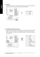
13)
SUR_CEN (Surround Center Connector)
Please contact your nearest dealer for optional 6-Channel Audio Combo Kit.
Pin No.
Definition
1
SUR OUTL
2
SUR OUTR
3
GND
4
No Pin
5
CENTER_OUT
6
BASS_OUT
14)
F_USB1 / F_USB2 (Front USB Connectors)
Be careful with the polarity of the front USB connector. Check the pin assignment carefully while
you connect the front USB cable, incorrect connection between the cable and connector will make
the device unable to work or even damage it. For optional front USB cable, please contact your
local dealer.
Pin No.
Definition
1
Power(5V)
2
Power(5V)
3
USB0 DX-
4
USB1 Dy-
5
USB0 DX+
6
USB1 Dy+
7
GND
8
GND
9
No Pin
10
NC
1
9
2
10
1
6
5
2