Harman Kardon 1000 Owners Manual - Page 14
Rear Panel Connections
 |
View all Harman Kardon 1000 manuals
Add to My Manuals
Save this manual to your list of manuals |
Page 14 highlights
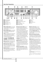
Rear Panel Connections 3 1 B Manufactured under license under U.S. Patent #'s: 5,451,942; 5,956,674; 5,974,380; 5,978,762; 6,487,535 & other U.S. and worldwide patents issued & pending. DTS is a registered trademark & the DTS logos and Symbol are trademarks of DTS, Inc. 1996-2007 DTS, Inc. All Rights Reserved. 9 C8 H A4 5 0 Optical Digital Output 1 Coaxial Digital Output 2 AC Power Cord 3 Composite Video Output 4 S-Video Output 5 Component Video Outputs 6 Scart TV Output 06 D FE7 G 2 I 7 Remote Control Output 8 Remote Control Input 9 Zone 2/3/4 Analog Audio Outputs A HDMI Output B Zone 1 Analog Audio Outputs C Analog Audio Input D The Bridge Connection E Network Jack F USB Port G RS-232 Port H Master Power Switch I Fan Vent 0 Optical Digital Output: Connect this jack to the optical digital input of an A/V receiver or surround processor for Dolby Digital, DTS or PCM audio playback. 1 Coaxial Digital Output: Connect this jack to the coaxial digital input of an A/V receiver or surround processor for Dolby Digital, DTS or PCM audio playback. NOTE: The coaxial digital output should only be connected to a digital input. Even though it is the same RCA-type connector as standard analog audio connections, DO NOT connect it to a conventional analog input jack. Connect either the Optical Digital Audio Output 0 or the Coaxial Digital Audio Output 1 to a corresponding digital audio input on your receiver or processor, but not both. 2 AC Power Cord: Connect this plug to an AC outlet. If the outlet is controlled by a switch, make certain that it is in the ON position. 3 Composite Video Output: Connect this jack to the video input on a television or video projector, or to a video input on an A/V receiver or processor if you are using that type of device for video input switching. 4 S-Video Output: Connect this jack to the S-Video input on a television or video projector, or to an S-Video input on an A/V receiver or processor if you are using that type of device for S-Video input switching. 5 Component Video Outputs: These outputs carry the component video signals for connection to display monitors with component video inputs. For standard analog TV's or projectors with inputs marked Y/Pr/Pb or Y/Cr/Cb, connect these outputs to the corresponding inputs. If you have a high-definition television or projector that is compatible with high scan rate progressive video, connect these jacks to the "HD Component" inputs. Note that if you are using a progressive scan display device, then "Progressive" must be selected in the Video Set-up Menu in order to take advantage of the progressive scan circuitry. See page 22 for more information on progressive scan video. IMPORTANT: These jacks should NOT be connected to standard composite video inputs. 6 SCART OUT (TV): If your TV has a SCART socket, you can connect a SCART cable to your TV and to your DMC 1000 Player for improved video quality. The SCART cable carries both audio and video. You can select Composite Video or RGB video for that SCART connector's video output signal. 7 Remote Control Output: Connect this jack to the infrared (IR) input jack of another compatible Harman Kardon remote controlled product to have the built-in Remote Sensor on the DMC 1000 provide IR signals to other compatible products. 8 Remote Control Input: Connect the output of a remote infrared sensor, or the remote control output of another compatible Harman Kardon product, to this jack. This will enable the remote control to operate even when the front panel Remote Sensor on the DMC 1000 is blocked. This jack may also be used with compatible IR remote control-based automation systems. 9 Zone 2/3/4 Analog Audio Outputs: When the DMC 1000 is being used for multizone operation, connect these jacks to the separate Zone inputs on your multiroom controller or hub, or the amplifiers feeding the multizone system. A HDMI Output: If you have an HDMI-compatible receiver or video display device, connect this output to an HDMI input on the receiver or video display for the highest-quality uncompressed digital audio and video available. Even if your receiver is not capable of processing audio in the HDMI format, you may still experience the superb reproduction of HDMI video. If your video display has a DVI input, you may use an optional HDMI-to-DVI cable or adapter for the connection to the display. In all cases, the video display must be HDCP-compliant in order to use the HDMI output. For best results, we do not recommend HDMI connections in excess of 3 meters.. The following audio formats may be output via the HDMI connection: Audio CD - 2-Channel PCM or 5.1-channel DTS DVD-Video - Up to 5.1-channel Dolby Digital or DTS 14 REAR PANEL CONNECTIONS
-
 1
1 -
2
-
3
-
4
-
5
-
6
-
7
-
8
-
 9
9 -
 10
10 -
 11
11 -
 12
12 -
 13
13 -
 14
14 -
 15
15 -
 16
16 -
 17
17 -
 18
18 -
 19
19 -
20
-
21
-
22
-
23
-
24
-
25
-
26
-
27
-
28
-
29
-
30
-
31
-
32
-
33
-
34
-
35
-
36
-
37
-
38
-
39
-
40
-
41
-
42
 |
 |
