Hayward TriStar VS TriStar VS Manual - Page 12
Interface Wall Mounting - wiring diagram
 |
View all Hayward TriStar VS manuals
Add to My Manuals
Save this manual to your list of manuals |
Page 12 highlights
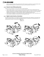
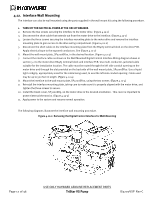
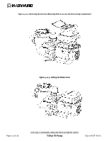
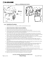
4.12. Interface Wall Mounting The interface can also be wall mounted using the parts supplied in the wall mount kit using the following procedure. 1. TURN OFF THE ELECTRICAL POWER AT THE CIRCUIT BREAKER. 2. Remove the two screws securing the interface to the motor drive. (Figure 4.12-1) 3. Disconnect the short cable that extends out from the motor drive to the interface. (Figure 4.12-1) 4. Loosen the three screws securing the interface mounting plate to the motor drive and remove the interface mounting plate to gain access to the drive wiring compartment. (Figure 4.12-2) 5. Disconnect the short cable on the interface mounting plate from the RS485 terminal block on the drive PCB. Apply electrical tape to the exposed conductors. See (Figure 4.12-2) 6. Mount the wall mount plate, SP3200DR10, in the desired location. (Figure 4.12-4) 7. Connect the interface cable as shown in the Wall Mounted Digital Control Interface Wiring diagram shown in section 5.2 to the motor drive RS485 terminal block and interface PCB. Use multi-conductor, jacketed cable suitable for the installation location. The cable must be routed through the left side conduit opening on the motor drive and through the slot provided on the backside of the wall mount plate, SP3200DR10. Use a liquid tight cordgrip, appropriately sized for the cable being used, to seal the left side conduit opening. Cable used may be up to 500 feet in length. (Figure 4.12-4) 8. Mount the interface to the wall mount plate, SP3200DR10, using the two screws. (Figure 4.12-4) 9. Reinstall the interface mounting plate, taking care to make sure it is properly aligned with the motor drive, and tighten the three screws to secure. 10. Install the blank cover, SP3200DR9, on the motor drive in the desired orientation. This cover is important to protect internal electronics. (Figure 4.12-3) 11. Apply power to the system and resume normal operation. The following diagrams illustrate the interface wall mounting procedure. Figure 4.12-1: Removing the Digital Control Interface for Wall Mounting Page 12 of 36 USE ONLY HAYWARD GENUINE REPLACEMENT PARTS TriStar VS Pump IS3200VSP Rev-C
-
 1
1 -
2
-
3
-
4
-
5
-
6
-
 7
7 -
 8
8 -
 9
9 -
 10
10 -
 11
11 -
 12
12 -
 13
13 -
 14
14 -
 15
15 -
 16
16 -
 17
17 -
18
-
19
-
20
-
21
-
22
-
23
-
24
-
25
-
26
-
27
-
28
-
29
-
30
-
31
-
32
-
33
-
34
-
35
-
36
 |
 |
