Hayward Universal H-Series Low NOx Service/Installation: H150FDN H200FDN H25 - Page 12
Flooring, Tie-down Brackets, Installing Tie-down Brackets
 |
View all Hayward Universal H-Series Low NOx manuals
Add to My Manuals
Save this manual to your list of manuals |
Page 12 highlights
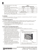
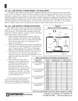
12 6. Do not install within 24" of any outdoor Table 1 HVAC equipment. 7. Do not install where water may run-off a roof into the heater. A gutter may be needed to protect the heater. Outdoor Installation Clearances Heater Panel Required Clearance Top Unobstructed 8. Any enclosure around the heater must Front 24 inches provide a combustion air vent commencing Back 6 inches within 12 inches of the bottom of the enclo- Water Connection Side 12 inches sure. The vent opening shall have a mini- Side Opposite Water Connection 6 inches mum free area of 1 square inch per 4,000 btu/hr input rating of all gas appliances in the enclosure. See Table 4. Flooring: This heater may be installed on either non-combustible or combustible flooring. Ultralite™ or equivalent concrete-over-foam HVAC pads are acceptable. Tie-down brackets: The heater is equipped for installation of factory-supplied tie-down brackets if required by local codes. The brackets are shipped in the consumer kit. You will need the following to complete the installation: 1. Tie-down brackets (factory-supplied, quantity = 4) 2. Sheet metal screws (factory-supplied, quantity = 4) 3. Concrete tapping screws (tapcons) (field-supplied, quantity = 4, size to be ¼" diameter with a minimum length of 2") Installing tie-down brackets: 1. Locate the tie-down brackets and the sheet metal screws. 2. Obtain the tap-cons. Be sure the overall length of the concrete tapping screw is at least 2". 3. Remove the front access panel (4 screws). 4. Remove the rear access panel (4 screws). 5. Position the heater on the pad so that all tap- cons can "bite" into the pad. Observe local codes regarding pad construction, some jurisdictions Figure 5 Install sheet metal screws (supplied) at these locations (front and rear) specify a minimum thickness for concrete pads. 6. Slip the tie-down brackets into the slots in the front of the heater base pan from underside of the heater, so that they are positioned as shown in figure 5. Install the sheet metal screws through the holes in the bracket to secure the bracket to the heater base pan. 7. Install the tap-cons through the holes in the tie- down brackets into the pad. 8. Repeat Steps 6 & 7 at the rear of the heater. Equipment pad 9. Installation is completed when (4) brackets are secured to the heater and the pad. Install the access panels when complete. Install concrete tapping screws (field-supplied) at these locations (front and rear) USE ONLY HAYWARD GENUINE REPLACEMENT PARTS Pomona, CA Clemmons, NC Nashville, TN Tel: 908-351-5400 www.haywardpool.com
-
 1
1 -
2
-
3
-
4
-
5
-
6
-
 7
7 -
 8
8 -
 9
9 -
 10
10 -
 11
11 -
 12
12 -
 13
13 -
 14
14 -
 15
15 -
 16
16 -
 17
17 -
18
-
19
-
20
-
21
-
22
-
23
-
24
-
25
-
26
-
27
-
28
-
29
-
30
-
31
-
32
-
33
-
34
-
35
-
36
-
37
-
38
-
39
-
40
-
41
-
42
-
43
-
44
-
45
-
46
-
47
-
48
-
49
-
50
-
51
-
52
-
53
-
54
-
55
-
56
-
57
-
58
-
59
-
60
-
61
-
62
-
63
-
64
 |
 |
