Hayward Universal H-Series Low NOx Service/Installation: H150FDN H200FDN H25 - Page 14
All Air Supply From Inside The Building, All Air Supply From Outdoors - heater - natural gas
 |
View all Hayward Universal H-Series Low NOx manuals
Add to My Manuals
Save this manual to your list of manuals |
Page 14 highlights
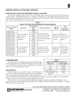
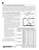
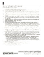
14 (A) All Air Supply From Inside the Building: The confined space shall be provided with 2 permanent openings communicating directly with an additional room(s) of sufficient volume so that the combined volume of all spaces meets the criteria for an unconfined space (a space whose volume is not less than 50 cubic feet per 1,000 btu/hr). The total input of all gas utilization equipment installed in the combined space shall be considered in making the determination. Each opening shall have a minimum free area of 1 square inch per 1,000 btu/hr of the total input rating of all gas utilization equipment in the confined space, but not less than 100 square inches. See Table 4. One opening shall be within 12 inches of the top and and one within 12 inches of the bottom of the enclosure. (B) All Air Supply From Outdoors: Figure 9 The confined space shall be provided with 2 permanent openings, once commencing within 12 inches of the bottom Below-BGelorwo-GuronuFdnigdu((rPPeit9)iItn)staIlnlatsiotnallation of the enclosure. The opening shall communicate directly, or by ducts, with the outdoors or spaces (crawl or attic) that freely communicate with the outdoors. Ventilation Air Vent Cap Ground Level Combustion Air 1. When communicating with the outdoors (either di- rectly or through vertical ducts), each opening shall have a minimum free area of 1 square inch per 4,000 Rise of 1 inch per foot Air Duct from Ground to Base btu/hr of total input rating of all equipment in the enclosure. See Table 4. 2. When communicating with the outdoors through hori- Drip Tee zontal ducts, each opening shall have a minimum free area of 1 square inch per 2,000 btu/hr of total input Gas Cock rating of all equipment in the enclosure. See Table 4. 3. When ducts are used, they shall be of the same cross- sectional area as the free area of the openings to which they connect. The minimum dimension of rect- Sediment Trap Level Flooring or Slab angular air ducts shall not be less than 3 inches. Table 4: Combustion and Ventilation Air Requirements 4. When installing a heater below Free Area per Btu Total Input Combustion Air Free Ventilation Air Free ground (in a pit), combustion and ventilation air openings must be provided as shown in Figure 9. Requirement 1 sq. in. per 1,000 btu/hr (paragraph A) (btu/hr) 150,000 200,000 250,000 Area Required (sq. in.) 150 200 250 Area Required (sq. in.) 150 200 250 Each opening shall have a minimum free area of 1 square inch per 300,000 300 300 350,000 350 350 400,000 400 400 250 btu/hr or total input rating of all equipment in the pit. See Table 1 sq. in. per 2,000 btu/hr (paragraph B-2) 150,000 200,000 250,000 75 100 125 75 100 125 4. Below-ground (pit) installations 300,000 150 150 must be natural gas only. 350,000 175 175 400,000 200 200 For more detailed methods of providing air for combustion and ventilation, 1 sq. in. per 4,000 btu/hr (paragraph B-1) 150,000 200,000 250,000 300,000 37.5 50 62.5 75 37.5 50 62.5 75 refer to the latest edition of the National 350,000 87.5 87.5 Fuel Gas Code (ANSI Z223.1/NFPA 54). 1 sq. in. per 250 btu/hr 400,000 150,000 100 600 100 600 (paragraph B-4) 200,000 250,000 800 1000 800 1000 300,000 1200 1200 350,000 1400 1400 400,000 1600 1600 USE ONLY HAYWARD GENUINE REPLACEMENT PARTS Pomona, CA Clemmons, NC Nashville, TN Tel: 908-351-5400 www.haywardpool.com
-
 1
1 -
2
-
3
-
4
-
5
-
6
-
7
-
8
-
 9
9 -
 10
10 -
 11
11 -
 12
12 -
 13
13 -
 14
14 -
 15
15 -
 16
16 -
 17
17 -
 18
18 -
 19
19 -
20
-
21
-
22
-
23
-
24
-
25
-
26
-
27
-
28
-
29
-
30
-
31
-
32
-
33
-
34
-
35
-
36
-
37
-
38
-
39
-
40
-
41
-
42
-
43
-
44
-
45
-
46
-
47
-
48
-
49
-
50
-
51
-
52
-
53
-
54
-
55
-
56
-
57
-
58
-
59
-
60
-
61
-
62
-
63
-
64
 |
 |
