Hayward Universal H-Series Low NOx Service/Installation: H150FDN H200FDN H25 - Page 26
Allowable Water Flow Rate Range, Manual Bypass valve - pool heater manual
 |
View all Hayward Universal H-Series Low NOx manuals
Add to My Manuals
Save this manual to your list of manuals |
Page 26 highlights
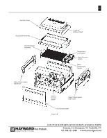
26 If the normal pump and filter system flow rate exceeds 125 gpm then a manual bypass valve must be installed as shown in Figure 21. Damage caused by flow rates outside this range will void the manufacturer's warranty. The installation is as follows: 1. Install a flow meter on the outlet line of the heater. 2. Adjust the manual bypass valve until the flow rate is within the flow rate range specified for the heater. 3. Once the valve is set, note the position and remove the valve handle to prevent further adjustment. Figure 20 Allowable Water Flow Rate Range Model Minimum Flow Maximum Flow Rate (GPM) Rate (GPM) H150FD H200FD 20 125 H250FD H300FD 25 125 H350FD H400FD 30 125 ATTENTION: Improperly adjusted manual bypass valves will result in damage to the heater if the flow rates are not maintained as specified in Figure 20 under all operating conditions. The heat ex- changer will fail and this damage will not be covered under the Hayward warranty. Figure 22 illustrates a typical pool piping diagram and layout for the pool equipment. Figure 23 illustrates a multiple heater installation for very large pools with and without a manual bypass valve. Figure 21: Manual Bypass valve USE ONLY HAYWARD GENUINE REPLACEMENT PARTS Pomona, CA Clemmons, NC Nashville, TN Tel: 908-351-5400 www.haywardpool.com
-
 1
1 -
2
-
3
-
4
-
5
-
6
-
7
-
8
-
9
-
10
-
11
-
12
-
13
-
14
-
15
-
16
-
17
-
18
-
19
-
20
-
 21
21 -
 22
22 -
 23
23 -
 24
24 -
 25
25 -
 26
26 -
 27
27 -
 28
28 -
 29
29 -
 30
30 -
 31
31 -
32
-
33
-
34
-
35
-
36
-
37
-
38
-
39
-
40
-
41
-
42
-
43
-
44
-
45
-
46
-
47
-
48
-
49
-
50
-
51
-
52
-
53
-
54
-
55
-
56
-
57
-
58
-
59
-
60
-
61
-
62
-
63
-
64
 |
 |
