Hayward Universal H-Series Low NOx Service/Installation: H150FDN H200FDN H25 - Page 18
Vent Kit Installation Procedure - heater schematic
 |
View all Hayward Universal H-Series Low NOx manuals
Add to My Manuals
Save this manual to your list of manuals |
Page 18 highlights
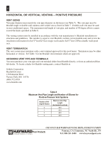
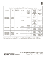
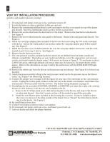
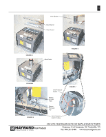
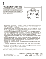
18 VENT KIT INSTALLATION PROCEDURE (positive and negative-pressure venting) 1. If connected, turn pump, main gas valve, and heater power off. 2. Locate the heater as close as practical to the gas vent exit. 3. Remove the countersunk phillips-head screws and remove the flue cover panel on top of the heater and discard. Save the countersunk screws as they will be re-used later. 4. Remove the screws that fasten the heat barrier to the heater. Remove the heat barrier and discard. See Figure 4. 5. Remove the screws that fasten the rain guard to the heater. Remove the rain guard and discard. See Figure 4. 6. Install the vent pipe adapter plate included in the kit into the heater using the #10 screws included with the kit. Ensure the white gaskets are in place under the vent pipe adapter plate before installing. See Figure 5. 7. Install the new flue cover included with the kit over the vent pipe adapter and secure with the countersunk screws from step 3 above. See Figure 6. 8. Remove heater front access door. 9. The vent pressure switches included with the indoor kit are labeled based on heater model and altitude compatibility. Depending on your model and altitude, select the appropriate vent pressure switch, and install inside the heater using 2 #10 screws as shown in Figure 7. If your heater is above 2,000 ft elevation, other high-altitude conversion steps may be necessary for proper heater performance. Refer to the information on page 8 and/or the instructions with the FDXLHAK1930 highaltitude kit. 10. Remove the rubber cap from the blower outlet pressure tap and discard. See Figure 8 for blower tap location. 11. Attach the pressure switch tubing to the vent pressure switch and to the pressure tap on the blower outlet. See Figure 8 for blower tap location. 12. Connect the jumper wire included with the indoor kit onto one of the terminals on the vent pressure switch. Unplug the in-line quick connect on the red wire in the heater wire harness, and connect the vent pressure switch in series with the red wire. See heater wiring schematic on page 28. 13. If installing the kit on models H250FDN, H250FDP, or H400FDP, you must also replace the existing blower air inlet restrictor with the new one included in the kit. a. Remove the 4 #10 hex head screws that fasten the plate to the blower, and remove the blower air plate and discard. Save the 4 screws as they will be needed to install the new plate. b. Install the new blower plate included in the kit using the 4 screws. It may be helpful to drive the screws in and out of the plate outside of the heater first to "thread" the holes before installing it in the heater. See Figure 8. 14. Re-install heater front door. 15. Connect vent piping system to heater vent adapter. 16. If connected, turn pump, main gas valve, and heater power back on. 17. Activate heater and check for proper function. USE ONLY HAYWARD GENUINE REPLACEMENT PARTS Pomona, CA Clemmons, NC Nashville, TN Tel: 908-351-5400 www.haywardpool.com
-
 1
1 -
2
-
3
-
4
-
5
-
6
-
7
-
8
-
9
-
10
-
11
-
12
-
 13
13 -
 14
14 -
 15
15 -
 16
16 -
 17
17 -
 18
18 -
 19
19 -
 20
20 -
 21
21 -
 22
22 -
 23
23 -
24
-
25
-
26
-
27
-
28
-
29
-
30
-
31
-
32
-
33
-
34
-
35
-
36
-
37
-
38
-
39
-
40
-
41
-
42
-
43
-
44
-
45
-
46
-
47
-
48
-
49
-
50
-
51
-
52
-
53
-
54
-
55
-
56
-
57
-
58
-
59
-
60
-
61
-
62
-
63
-
64
 |
 |
