HP 11-p100 x360 Convertible PC model numbers 11-p100 through p199 Maintenance - Page 33
bottom cover.
 |
View all HP 11-p100 manuals
Add to My Manuals
Save this manual to your list of manuals |
Page 33 highlights
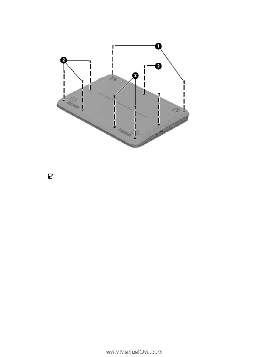
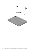
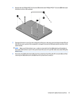
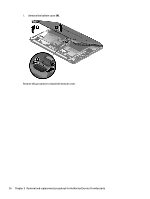
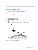
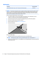
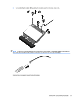
4. Remove the two Phillips PM2.5×8.0 screws (1) and the seven Phillips PM2.0×7.0 screws (2) that secure the bottom cover to the computer. 5. Separate the bottom cover from the computer by lifting up at the seam near the display hinges (1), and then lift the cover up and off the computer far enough to access the USB/audio board connector on the system board. NOTE: When you lift the bottom cover, a cable is connected from the USB/audio board (installed on the inside of the bottom cover) to the system board. Be sure not to pull the cable loose when lifting the bottom cover. 6. Disconnect the USB/audio board cable from the system board by lifting the ZIF connector (2), and then removing the USB/audio board cable (3) from the system board connector. Component replacement procedures 25
-
 1
1 -
2
-
3
-
4
-
5
-
6
-
7
-
8
-
9
-
10
-
11
-
12
-
13
-
14
-
15
-
16
-
17
-
18
-
19
-
20
-
21
-
22
-
23
-
24
-
25
-
26
-
27
-
 28
28 -
 29
29 -
 30
30 -
 31
31 -
 32
32 -
 33
33 -
 34
34 -
 35
35 -
 36
36 -
 37
37 -
 38
38 -
39
-
40
-
41
-
42
-
43
-
44
-
45
-
46
-
47
-
48
-
49
-
50
-
51
-
52
-
53
-
54
-
55
-
56
-
57
-
58
-
59
-
60
-
61
-
62
-
63
-
64
-
65
-
66
-
67
-
68
-
69
-
70
-
71
-
72
-
73
-
74
 |
 |