HP 11-p100 x360 Convertible PC model numbers 11-p100 through p199 Maintenance - Page 50
CAUTION, Support the display assembly when removing the screws. Failure to support the display
 |
View all HP 11-p100 manuals
Add to My Manuals
Save this manual to your list of manuals |
Page 50 highlights
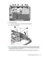
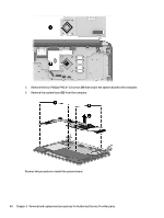
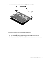
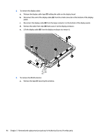
4. Disconnect the display cable (4) from the system board. 5. Remove the two silver Phillips PM2.5×4.0 screws (1) and the two black Phillips PM2.5×5.0 screws (2) that secure the display assembly and bracket to the computer. CAUTION: Support the display assembly when removing the screws. Failure to support the display assembly can result in damage to the display assembly and other computer components. 42 Chapter 5 Removal and replacement procedures for Authorized Service Provider parts
-
 1
1 -
2
-
3
-
4
-
5
-
6
-
7
-
8
-
9
-
10
-
11
-
12
-
13
-
14
-
15
-
16
-
17
-
18
-
19
-
20
-
21
-
22
-
23
-
24
-
25
-
26
-
27
-
28
-
29
-
30
-
31
-
32
-
33
-
34
-
35
-
36
-
37
-
38
-
39
-
40
-
41
-
42
-
43
-
44
-
 45
45 -
 46
46 -
 47
47 -
 48
48 -
 49
49 -
 50
50 -
 51
51 -
 52
52 -
 53
53 -
 54
54 -
 55
55 -
56
-
57
-
58
-
59
-
60
-
61
-
62
-
63
-
64
-
65
-
66
-
67
-
68
-
69
-
70
-
71
-
72
-
73
-
74
 |
 |

4.
Disconnect the display cable
(4)
from the system board.
5.
Remove the two silver Phillips PM2.5×4.0 screws
(1)
and the two black Phillips PM2.5×5.0 screws
(2)
that secure the display assembly and bracket to the computer.
CAUTION:
Support the display assembly when removing the screws. Failure to support the display
assembly can result in damage to the display assembly and other computer components.
42
Chapter 5
Removal and replacement procedures for Authorized Service Provider parts