HP 14-g000 Maintenance and Service Guide - Page 58
Display subcomponents (bezel, webcam, panel), Remove the two Mylar covers
 |
View all HP 14-g000 manuals
Add to My Manuals
Save this manual to your list of manuals |
Page 58 highlights
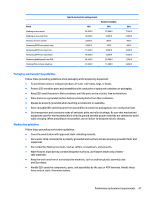
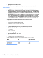
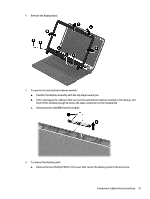
Display subcomponents (bezel, webcam, panel) This section describes removing display subcomponents that do not require that you remove the entire display assembly from the computer. You can remove the display bezel, webcam/microphone module, and display panel while the display assembly is still attached to the computer. To remove the remaining display subcomponents, you must remove the entire display assembly from the computer. See Display assembly on page 76 for more information about removing the display assembly in its entirety. Description Raw display panel for use in HP 14 and Compaq 14 models without a touch screen Raw display panel for use in HP 240 G3 models without a touch screen Raw display panel for use in HP 245 G3 models with a touch screen Raw display panel for use in HP 14 models, touch screen Raw display panel for use in Compaq 14 models, touch screen Display bezel for use with HP 14 models Display bezel for use with HP 240/246 G3 models Display bezel for use with HP 245 G3 models Display bezel for use with Compaq 14 models Webcam/microphone module, HD Webcam/microphone module, VGA Spare part number 760105-001 766010-001 778156-001 760106-001 757611-001 757599-001 766009-001 766900-001 757600-001 757614-001 781623-001 Before removing display subcomponents while the display assembly is still attached to the computer, follow these steps: 1. Shut down the computer. If you are unsure whether the computer is off or in Hibernation, turn the computer on, and then shut it down through the operating system. 2. Disconnect all external devices connected to the computer. 3. Disconnect the power from the computer by first unplugging the power cord from the AC outlet and then unplugging the AC adapter from the computer. 4. Remove the battery (see Battery on page 49). To remove the display bezel, webcam/microphone module, and raw display panel: 1. Position the computer upright with the front toward you, and then open it. 2. Remove the two Mylar covers (1) and two Phillips PM2.0×3.0 screws (2) that secure the bezel to the display. 3. Flex the inside of the top edge (3), the left and right sides (4), and the bottom edge (5) of the display bezel until the bezel disengages from the display enclosure. 50 Chapter 4 Removal and replacement procedures
-
 1
1 -
2
-
3
-
4
-
5
-
6
-
7
-
8
-
9
-
10
-
11
-
12
-
13
-
14
-
15
-
16
-
17
-
18
-
19
-
20
-
21
-
22
-
23
-
24
-
25
-
26
-
27
-
28
-
29
-
30
-
31
-
32
-
33
-
34
-
35
-
36
-
37
-
38
-
39
-
40
-
41
-
42
-
43
-
44
-
45
-
46
-
47
-
48
-
49
-
50
-
51
-
52
-
 53
53 -
 54
54 -
 55
55 -
 56
56 -
 57
57 -
 58
58 -
 59
59 -
 60
60 -
 61
61 -
 62
62 -
 63
63 -
64
-
65
-
66
-
67
-
68
-
69
-
70
-
71
-
72
-
73
-
74
-
75
-
76
-
77
-
78
-
79
-
80
-
81
-
82
-
83
-
84
-
85
-
86
-
87
-
88
-
89
-
90
-
91
-
92
-
93
-
94
-
95
-
96
-
97
-
98
-
99
-
100
-
101
-
102
-
103
-
104
-
105
-
106
-
107
-
108
-
109
-
110
-
111
-
112
-
113
-
114
-
115
-
116
-
117
-
118
-
119
-
120
-
121
-
122
-
123
-
124
-
125
-
126
-
127
-
128
-
129
-
130
-
131
-
132
-
133
-
134
-
135
-
136
-
137
-
138
-
139
-
140
-
141
-
142
-
143
-
144
-
145
-
146
-
147
-
148
 |
 |