HP 14-g000 Maintenance and Service Guide - Page 85
CAUTION, Disconnect the display panel cable from the system board
 |
View all HP 14-g000 manuals
Add to My Manuals
Save this manual to your list of manuals |
Page 85 highlights
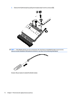
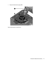
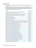
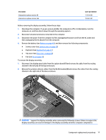
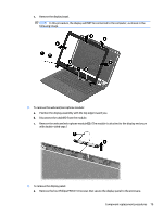
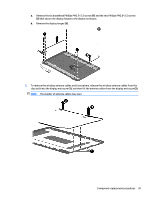
Description Webcam/microphone module, HD Webcam/microphone module, VGA Spare part number 757614-001 781623-001 Before removing the display assembly, follow these steps: 1. Shut down the computer. If you are unsure whether the computer is off or in Hibernation, turn the computer on, and then shut it down through the operating system. 2. Disconnect all external devices connected to the computer. 3. Disconnect the power from the computer by first unplugging the power cord from the AC outlet and then unplugging the AC adapter from the computer. 4. Remove the battery (see Battery on page 49), and then remove the following components: ● Service cover (see Service cover on page 55) ● Keyboard (see Keyboard on page 57) ● Top cover (see Top cover on page 60) ● Fan (see Fan on page 74) To remove the display assembly: 1. Disconnect the display panel cable from the system board (1) and remove the cable from the routing channel in the left side of the base enclosure. 2. Release the wireless antenna cables from the WLAN module (2) and remove the cables from the routing channel in the right side of the base enclosure. CAUTION: Support the display assembly when removing the following screws. Failure to support the display assembly can result in damage to the display assembly and other computer components. Component replacement procedures 77
-
 1
1 -
2
-
3
-
4
-
5
-
6
-
7
-
8
-
9
-
10
-
11
-
12
-
13
-
14
-
15
-
16
-
17
-
18
-
19
-
20
-
21
-
22
-
23
-
24
-
25
-
26
-
27
-
28
-
29
-
30
-
31
-
32
-
33
-
34
-
35
-
36
-
37
-
38
-
39
-
40
-
41
-
42
-
43
-
44
-
45
-
46
-
47
-
48
-
49
-
50
-
51
-
52
-
53
-
54
-
55
-
56
-
57
-
58
-
59
-
60
-
61
-
62
-
63
-
64
-
65
-
66
-
67
-
68
-
69
-
70
-
71
-
72
-
73
-
74
-
75
-
76
-
77
-
78
-
79
-
 80
80 -
 81
81 -
 82
82 -
 83
83 -
 84
84 -
 85
85 -
 86
86 -
 87
87 -
 88
88 -
 89
89 -
 90
90 -
91
-
92
-
93
-
94
-
95
-
96
-
97
-
98
-
99
-
100
-
101
-
102
-
103
-
104
-
105
-
106
-
107
-
108
-
109
-
110
-
111
-
112
-
113
-
114
-
115
-
116
-
117
-
118
-
119
-
120
-
121
-
122
-
123
-
124
-
125
-
126
-
127
-
128
-
129
-
130
-
131
-
132
-
133
-
134
-
135
-
136
-
137
-
138
-
139
-
140
-
141
-
142
-
143
-
144
-
145
-
146
-
147
-
148
 |
 |