HP 14t-r000 HP 14 Notebook PC Compaq 14 Notebook PC HP 240 G3 Notebook PC HP 2 - Page 55
Disconnect the cable, To remove the display panel
 |
View all HP 14t-r000 manuals
Add to My Manuals
Save this manual to your list of manuals |
Page 55 highlights
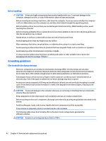
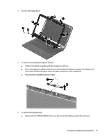
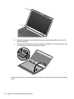
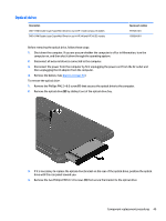
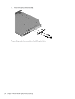
4. Remove the display bezel. 5. To remove the webcam/microphone module: a. Position the display assembly with the top edge toward you. b. Lift to disengage the adhesive that secures the webcam/microphone module to the display, and then lift the module enough to access the cable connection on the module (1). c. Disconnect the cable (2) from the module. 6. To remove the display panel: a. Remove the four Phillips PM2.0×3.0 screws that secure the display panel to the enclosure. Component replacement procedures 47
-
 1
1 -
2
-
3
-
4
-
5
-
6
-
7
-
8
-
9
-
10
-
11
-
12
-
13
-
14
-
15
-
16
-
17
-
18
-
19
-
20
-
21
-
22
-
23
-
24
-
25
-
26
-
27
-
28
-
29
-
30
-
31
-
32
-
33
-
34
-
35
-
36
-
37
-
38
-
39
-
40
-
41
-
42
-
43
-
44
-
45
-
46
-
47
-
48
-
49
-
 50
50 -
 51
51 -
 52
52 -
 53
53 -
 54
54 -
 55
55 -
 56
56 -
 57
57 -
 58
58 -
 59
59 -
 60
60 -
61
-
62
-
63
-
64
-
65
-
66
-
67
-
68
-
69
-
70
-
71
-
72
-
73
-
74
-
75
-
76
-
77
-
78
-
79
-
80
-
81
-
82
-
83
-
84
-
85
-
86
-
87
-
88
-
89
-
90
-
91
-
92
-
93
-
94
-
95
-
96
-
97
-
98
-
99
-
100
-
101
-
102
-
103
-
104
-
105
-
106
-
107
-
108
-
109
-
110
-
111
-
112
-
113
-
114
-
115
-
116
-
117
-
118
-
119
-
120
-
121
-
122
-
123
-
124
-
125
-
126
-
127
-
128
-
129
-
130
-
131
-
132
-
133
-
134
-
135
-
136
-
137
-
138
-
139
-
140
-
141
-
142
-
143
-
144
 |
 |
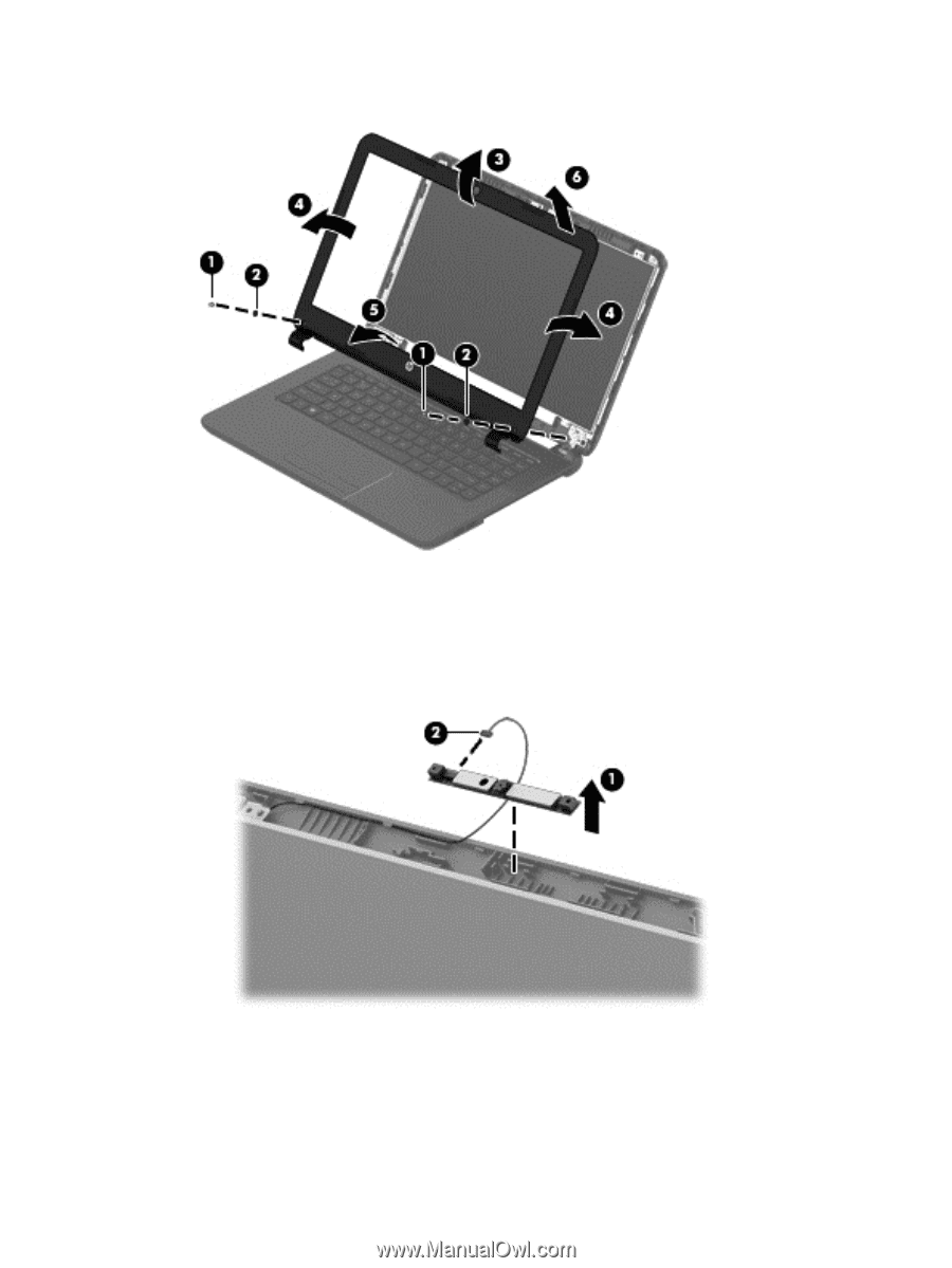
4.
Remove the display bezel.
5.
To remove the webcam/microphone module:
a.
Position the display assembly with the top edge toward you.
b.
Lift to disengage the adhesive that secures the webcam/microphone module to the display, and
then lift the module enough to access the cable connection on the module
(1)
.
c.
Disconnect the cable
(2)
from the module.
6.
To remove the display panel:
a.
Remove the four Phillips PM2.0×3.0 screws that secure the display panel to the enclosure.
Component replacement procedures
47