HP 14t-r000 HP 14 Notebook PC Compaq 14 Notebook PC HP 240 G3 Notebook PC HP 2 - Page 85
clips built into the display enclosure, To remove the wireless antenna cables and transceivers
 |
View all HP 14t-r000 manuals
Add to My Manuals
Save this manual to your list of manuals |
Page 85 highlights
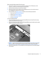
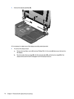
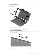
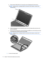
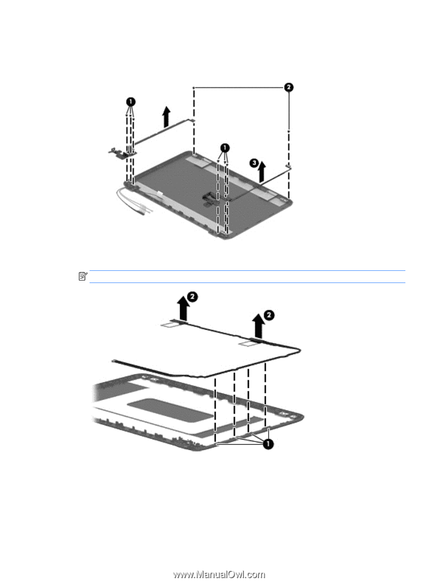
a. Remove the six broadhead Phillips PM2.5×2.5 screws (1) and the two Phillips PM2.0×2.5 screws (2) that secure the display hinges to the display enclosure. b. Remove the display hinges (3). 5. To remove the wireless antenna cables and transceivers, release the wireless antenna cables from the clips built into the display enclosure (1), and then lift the antenna cables from the display enclosure (2). NOTE: The number of antenna cables may vary. Component replacement procedures 77
-
 1
1 -
2
-
3
-
4
-
5
-
6
-
7
-
8
-
9
-
10
-
11
-
12
-
13
-
14
-
15
-
16
-
17
-
18
-
19
-
20
-
21
-
22
-
23
-
24
-
25
-
26
-
27
-
28
-
29
-
30
-
31
-
32
-
33
-
34
-
35
-
36
-
37
-
38
-
39
-
40
-
41
-
42
-
43
-
44
-
45
-
46
-
47
-
48
-
49
-
50
-
51
-
52
-
53
-
54
-
55
-
56
-
57
-
58
-
59
-
60
-
61
-
62
-
63
-
64
-
65
-
66
-
67
-
68
-
69
-
70
-
71
-
72
-
73
-
74
-
75
-
76
-
77
-
78
-
79
-
 80
80 -
 81
81 -
 82
82 -
 83
83 -
 84
84 -
 85
85 -
 86
86 -
 87
87 -
 88
88 -
 89
89 -
 90
90 -
91
-
92
-
93
-
94
-
95
-
96
-
97
-
98
-
99
-
100
-
101
-
102
-
103
-
104
-
105
-
106
-
107
-
108
-
109
-
110
-
111
-
112
-
113
-
114
-
115
-
116
-
117
-
118
-
119
-
120
-
121
-
122
-
123
-
124
-
125
-
126
-
127
-
128
-
129
-
130
-
131
-
132
-
133
-
134
-
135
-
136
-
137
-
138
-
139
-
140
-
141
-
142
-
143
-
144
 |
 |
a.
Remove the six broadhead Phillips PM2.5×2.5 screws
(1)
and the two Phillips PM2.0×2.5 screws
(2)
that secure the display hinges to the display enclosure.
b.
Remove the display hinges
(3)
.
5.
To remove the wireless antenna cables and transceivers, release the wireless antenna cables from the
clips built into the display enclosure
(1)
, and then lift the antenna cables from the display enclosure
(2)
.
NOTE:
The number of antenna cables may vary.
Component replacement procedures
77