HP 15-f200 Maintenance and Service Guide - Page 51
Remove the memory module see, WLAN module see
 |
View all HP 15-f200 manuals
Add to My Manuals
Save this manual to your list of manuals |
Page 51 highlights
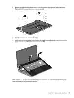
a. Optical drive (see Optical drive on page 33). b. Remove the service door (see Service door on page 29). c. Remove the WLAN module (see WLAN module on page 31). d. Remove the memory module (see Memory module on page 30). e. Keyboard (see Keyboard on page 38). Remove the top cover: 1. Remove the five Phillips M2.5×3.0 screws that secure the top cover to the base enclosure. Component replacement procedures 41
-
 1
1 -
2
-
3
-
4
-
5
-
6
-
7
-
8
-
9
-
10
-
11
-
12
-
13
-
14
-
15
-
16
-
17
-
18
-
19
-
20
-
21
-
22
-
23
-
24
-
25
-
26
-
27
-
28
-
29
-
30
-
31
-
32
-
33
-
34
-
35
-
36
-
37
-
38
-
39
-
40
-
41
-
42
-
43
-
44
-
45
-
 46
46 -
 47
47 -
 48
48 -
 49
49 -
 50
50 -
 51
51 -
 52
52 -
 53
53 -
 54
54 -
 55
55 -
 56
56 -
57
-
58
-
59
-
60
-
61
-
62
-
63
-
64
-
65
-
66
-
67
-
68
-
69
-
70
-
71
-
72
-
73
-
74
-
75
-
76
-
77
-
78
-
79
-
80
-
81
-
82
-
83
-
84
-
85
-
86
-
87
-
88
-
89
-
90
-
91
-
92
-
93
-
94
-
95
-
96
-
97
-
98
-
99
-
100
-
101
-
102
-
103
-
104
-
105
-
106
-
107
 |
 |

a.
Optical drive (see
Optical drive
on page
33
).
b.
Remove the service door (see
Service door
on page
29
).
c.
Remove the
WLAN module (see
WLAN module
on page
31
).
d.
Remove the memory module (see
Memory module
on page
30
).
e.
Keyboard (see
Keyboard
on page
38
).
Remove the top cover:
1.
Remove the
five
Phillips M2.5×3.0 screws that secure the top cover to the base enclosure.
Component replacement procedures
41