HP 15-f200 Maintenance and Service Guide - Page 53
Lift to remove the top cover, When replacing the top cover
 |
View all HP 15-f200 manuals
Add to My Manuals
Save this manual to your list of manuals |
Page 53 highlights
5. Remove the additional three Phillips M2.0×1.5 screws from the optical drive bay (1) and the three Phillips M2.5×6.5 screws from under the service door (2). 6. Turn the computer over and open the display. 7. Gently press on the right upper corner (1) where the display hinge and top cover meet. Lift around the edges of the top cover (2). Lift to remove the top cover (3). When replacing the top cover, be sure that the following components are removed from the defective top cover and installed on the replacement top cover: Component replacement procedures 43
-
 1
1 -
2
-
3
-
4
-
5
-
6
-
7
-
8
-
9
-
10
-
11
-
12
-
13
-
14
-
15
-
16
-
17
-
18
-
19
-
20
-
21
-
22
-
23
-
24
-
25
-
26
-
27
-
28
-
29
-
30
-
31
-
32
-
33
-
34
-
35
-
36
-
37
-
38
-
39
-
40
-
41
-
42
-
43
-
44
-
45
-
46
-
47
-
 48
48 -
 49
49 -
 50
50 -
 51
51 -
 52
52 -
 53
53 -
 54
54 -
 55
55 -
 56
56 -
 57
57 -
 58
58 -
59
-
60
-
61
-
62
-
63
-
64
-
65
-
66
-
67
-
68
-
69
-
70
-
71
-
72
-
73
-
74
-
75
-
76
-
77
-
78
-
79
-
80
-
81
-
82
-
83
-
84
-
85
-
86
-
87
-
88
-
89
-
90
-
91
-
92
-
93
-
94
-
95
-
96
-
97
-
98
-
99
-
100
-
101
-
102
-
103
-
104
-
105
-
106
-
107
 |
 |

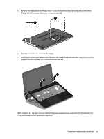
5.
Remove the additional three Phillips M2.0×1.5 screws from the optical drive bay
(1)
and the three
Phillips M2.5×6.5 screws from under the service door
(2)
.
6.
Turn the computer over and open the display.
7.
Gently press on the right upper corner
(1)
where the display hinge and top cover meet. Lift around the
edges of the top cover
(2)
. Lift to remove the top cover
(3)
.
When replacing the top cover, be sure that the following components are removed from the defective top
cover and installed on the replacement top cover:
Component replacement procedures
43