HP 2000-2100 Maintenance and Service Guide - Page 50
Reverse this procedure to install the WLAN module., Removal and replacement procedures
 |
View all HP 2000-2100 manuals
Add to My Manuals
Save this manual to your list of manuals |
Page 50 highlights
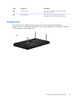
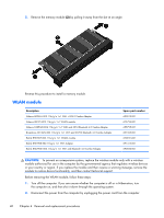
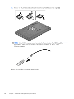
3. Remove the WLAN module by pulling the module away from the slot at an angle (3). NOTE: If the WLAN antennas are not connected to the terminals on the WLAN module, the protective sleeves must be installed on the antenna connectors, as shown in the following illustration. Reverse this procedure to install the WLAN module. 42 Chapter 4 Removal and replacement procedures
-
 1
1 -
2
-
3
-
4
-
5
-
6
-
7
-
8
-
9
-
10
-
11
-
12
-
13
-
14
-
15
-
16
-
17
-
18
-
19
-
20
-
21
-
22
-
23
-
24
-
25
-
26
-
27
-
28
-
29
-
30
-
31
-
32
-
33
-
34
-
35
-
36
-
37
-
38
-
39
-
40
-
41
-
42
-
43
-
44
-
 45
45 -
 46
46 -
 47
47 -
 48
48 -
 49
49 -
 50
50 -
 51
51 -
 52
52 -
 53
53 -
 54
54 -
 55
55 -
56
-
57
-
58
-
59
-
60
-
61
-
62
-
63
-
64
-
65
-
66
-
67
-
68
-
69
-
70
-
71
-
72
-
73
-
74
-
75
-
76
-
77
-
78
-
79
-
80
-
81
-
82
-
83
-
84
-
85
-
86
-
87
-
88
-
89
-
90
-
91
-
92
-
93
-
94
-
95
-
96
-
97
-
98
-
99
-
100
-
101
-
102
-
103
-
104
-
105
-
106
-
107
-
108
-
109
-
110
-
111
 |
 |
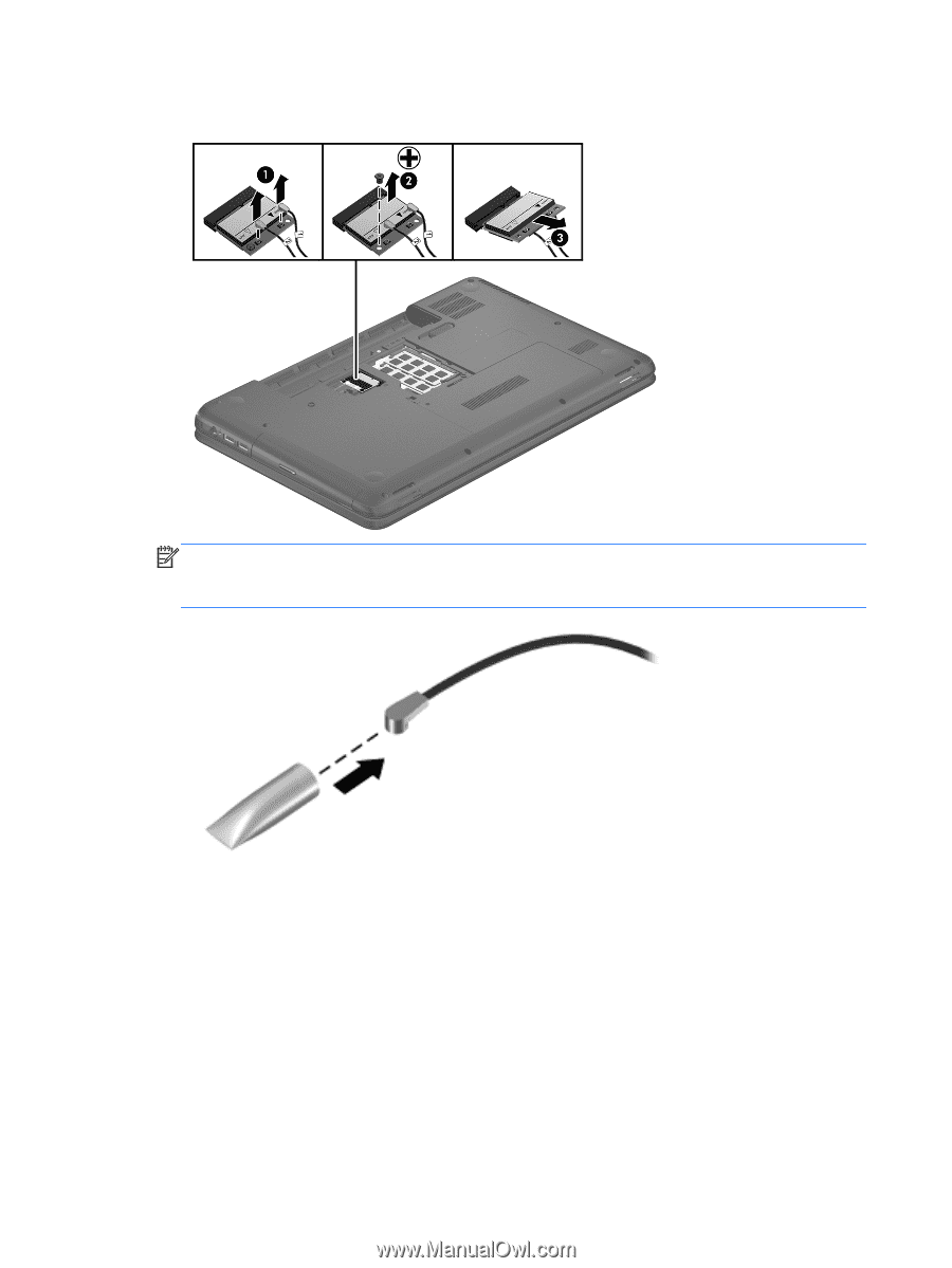
3.
Remove the WLAN module by pulling the module away from the slot at an angle
(3)
.
NOTE:
If the WLAN antennas are not connected to the terminals on the WLAN module,
the protective sleeves must be installed on the antenna connectors, as shown in the
following illustration.
Reverse this procedure to install the WLAN module.
42
Chapter 4
Removal and replacement procedures