HP 2000-2100 Maintenance and Service Guide - Page 90
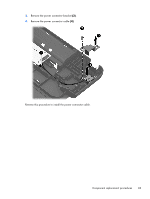
Power connector cable, Remove the Phillips PM2.5×6.5 screw
 |
View all HP 2000-2100 manuals
Add to My Manuals
Save this manual to your list of manuals |
Page 90 highlights
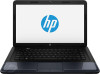
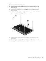
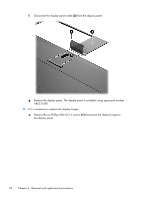
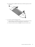
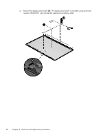
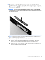
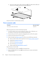
c. Remove the wireless antenna cables and transceivers (3). The wireless antenna cables and transceivers are available using spare part number 686249-001. Reverse this procedure to install the display assembly. Power connector cable Description Power connector cable (includes bracket) Spare part number 686258-001 Before removing the power connector cable, follow these steps: 1. Turn off the computer. If you are unsure whether the computer is off or in Hibernation, turn the computer on, and then shut it down through the operating system. 2. Disconnect the power from the computer by unplugging the power cord from the computer. 3. Disconnect all external devices from the computer. 4. Remove the battery (see Battery on page 38), and then remove the following components: a. Memory module/wireless module compartment cover (see Memory module on page 39) b. Keyboard (see Keyboard on page 43) c. Hard drive (see Hard drive on page 49) d. Top cover (see Top cover on page 53) e. Display assembly (see Display assembly on page 73) Remove the power connector cable: 1. Disconnect the power connector cable (1) from the system board. 2. Remove the Phillips PM2.5×6.5 screw (2) that secures the power connector and bracket to the base enclosure. 82 Chapter 4 Removal and replacement procedures
-
 1
1 -
2
-
3
-
4
-
5
-
6
-
7
-
8
-
9
-
10
-
11
-
12
-
13
-
14
-
15
-
16
-
17
-
18
-
19
-
20
-
21
-
22
-
23
-
24
-
25
-
26
-
27
-
28
-
29
-
30
-
31
-
32
-
33
-
34
-
35
-
36
-
37
-
38
-
39
-
40
-
41
-
42
-
43
-
44
-
45
-
46
-
47
-
48
-
49
-
50
-
51
-
52
-
53
-
54
-
55
-
56
-
57
-
58
-
59
-
60
-
61
-
62
-
63
-
64
-
65
-
66
-
67
-
68
-
69
-
70
-
71
-
72
-
73
-
74
-
75
-
76
-
77
-
78
-
79
-
80
-
81
-
82
-
83
-
84
-
 85
85 -
 86
86 -
 87
87 -
 88
88 -
 89
89 -
 90
90 -
 91
91 -
 92
92 -
 93
93 -
 94
94 -
 95
95 -
96
-
97
-
98
-
99
-
100
-
101
-
102
-
103
-
104
-
105
-
106
-
107
-
108
-
109
-
110
-
111
 |
 |
