HP 2000-2100 Maintenance and Service Guide - Page 78
The thermal material must be thoroughly cleaned from the surfaces of the processor heat sink
 |
View all HP 2000-2100 manuals
Add to My Manuals
Save this manual to your list of manuals |
Page 78 highlights
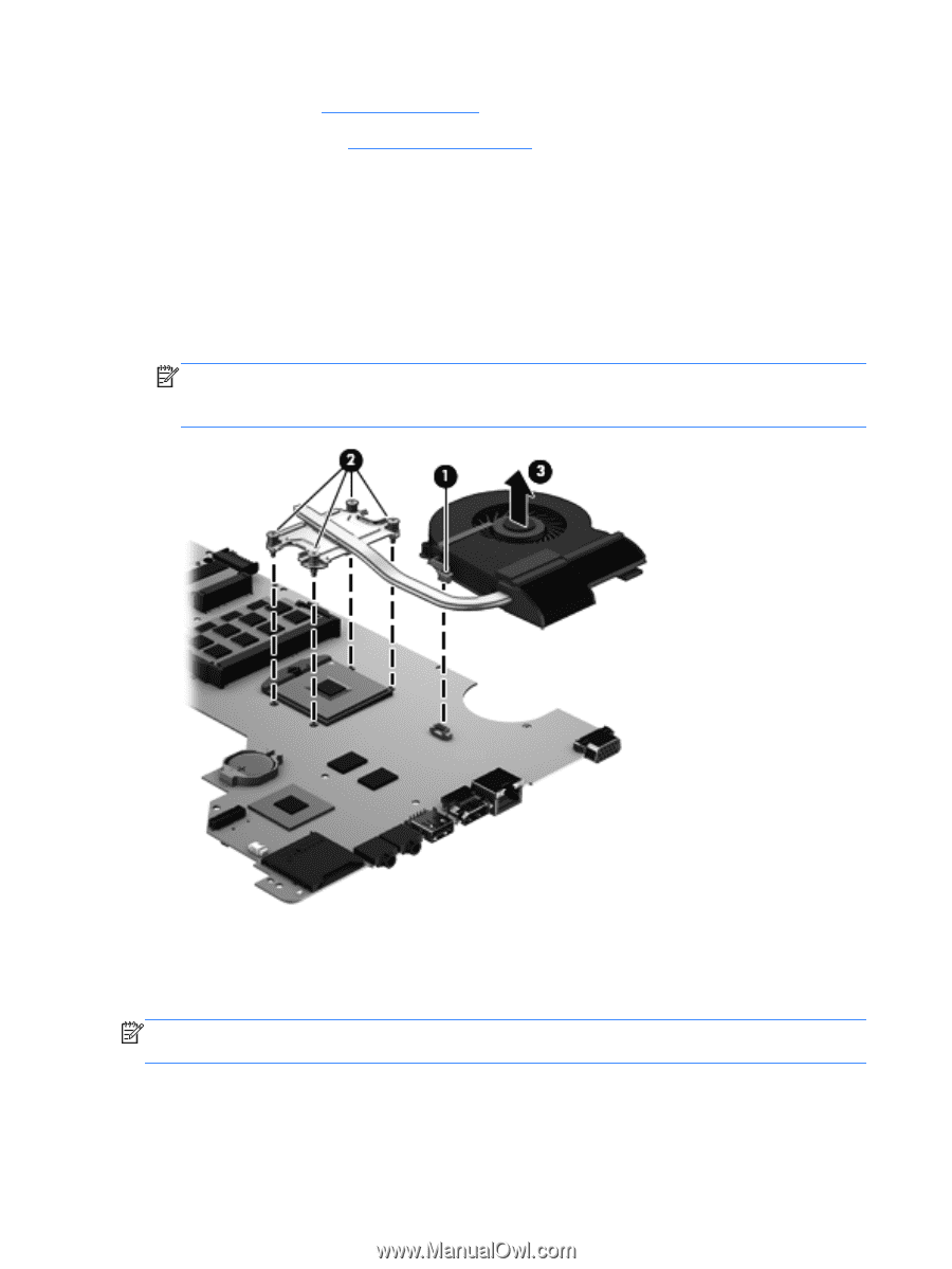
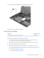
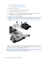
d. Top cover (see Top cover on page 53) e. System board (see System board on page 67) Remove the fan/heat sink assembly: 1. Turn the system board upside down, with the front toward you. 2. Disconnect the fan cable (1) from the system board. 3. Following the 1, 2, 3, 4 sequence stamped into the heat sink, loosen the four captive Philllips screws (2) that secure the fan/heat sink assembly to the system board. 4. Remove the fan/heat sink assembly (3). NOTE: Due to the adhesive quality of the thermal material located between the processor heat sink and processor, it may be necessary to move the processor heat sink from side to side to detach it. The thermal material must be thoroughly cleaned from the surfaces of the processor heat sink and the processor each time the processor heat sink is removed. Replacement thermal material is included with the processor heat sink and system board spare part kits. NOTE: The following illustration shows the replacement thermal material locations. Thermal paste is used on the processor (1) and the heat sink section (2) that services it. 70 Chapter 4 Removal and replacement procedures
-
 1
1 -
2
-
3
-
4
-
5
-
6
-
7
-
8
-
9
-
10
-
11
-
12
-
13
-
14
-
15
-
16
-
17
-
18
-
19
-
20
-
21
-
22
-
23
-
24
-
25
-
26
-
27
-
28
-
29
-
30
-
31
-
32
-
33
-
34
-
35
-
36
-
37
-
38
-
39
-
40
-
41
-
42
-
43
-
44
-
45
-
46
-
47
-
48
-
49
-
50
-
51
-
52
-
53
-
54
-
55
-
56
-
57
-
58
-
59
-
60
-
61
-
62
-
63
-
64
-
65
-
66
-
67
-
68
-
69
-
70
-
71
-
72
-
 73
73 -
 74
74 -
 75
75 -
 76
76 -
 77
77 -
 78
78 -
 79
79 -
 80
80 -
 81
81 -
 82
82 -
 83
83 -
84
-
85
-
86
-
87
-
88
-
89
-
90
-
91
-
92
-
93
-
94
-
95
-
96
-
97
-
98
-
99
-
100
-
101
-
102
-
103
-
104
-
105
-
106
-
107
-
108
-
109
-
110
-
111
 |
 |