HP 2000-2100 Maintenance and Service Guide - Page 76
Remove the system board, that secure the system board
 |
View all HP 2000-2100 manuals
Add to My Manuals
Save this manual to your list of manuals |
Page 76 highlights
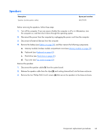
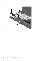
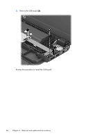
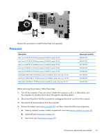
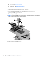
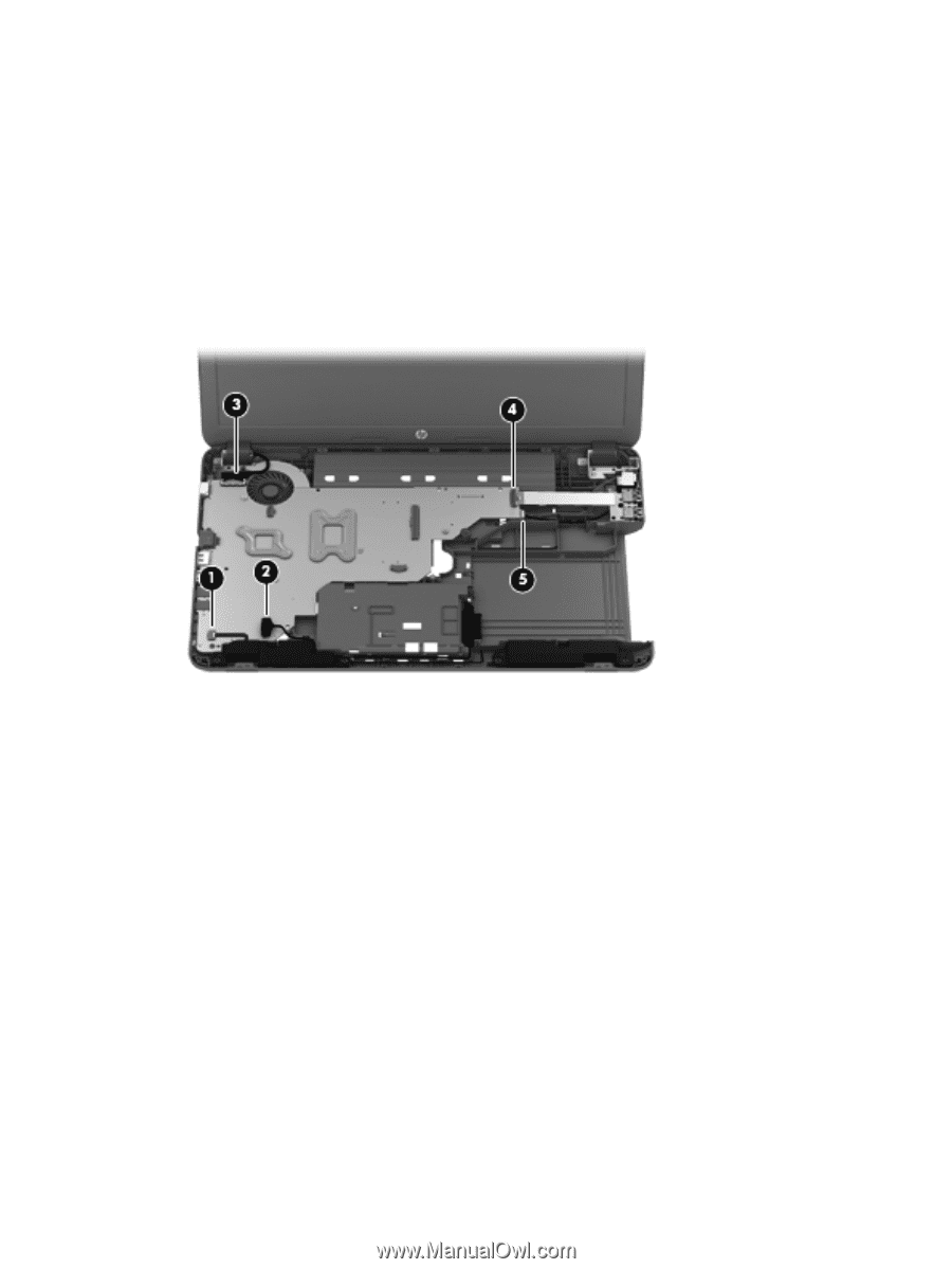
Remove the system board: 1. Disconnect the following cables from the system board. (1) Speaker cable (2) Optical drive connector cable (3) Display panel cable (4) USB board cable (5) Power connector cable 2. Remove the three Phillips PM2.5×6.0 screws (1) that secure the system board to the base enclosure. 3. Lift the right side of the system board (2) until it rests at an angle. 68 Chapter 4 Removal and replacement procedures
-
 1
1 -
2
-
3
-
4
-
5
-
6
-
7
-
8
-
9
-
10
-
11
-
12
-
13
-
14
-
15
-
16
-
17
-
18
-
19
-
20
-
21
-
22
-
23
-
24
-
25
-
26
-
27
-
28
-
29
-
30
-
31
-
32
-
33
-
34
-
35
-
36
-
37
-
38
-
39
-
40
-
41
-
42
-
43
-
44
-
45
-
46
-
47
-
48
-
49
-
50
-
51
-
52
-
53
-
54
-
55
-
56
-
57
-
58
-
59
-
60
-
61
-
62
-
63
-
64
-
65
-
66
-
67
-
68
-
69
-
70
-
 71
71 -
 72
72 -
 73
73 -
 74
74 -
 75
75 -
 76
76 -
 77
77 -
 78
78 -
 79
79 -
 80
80 -
 81
81 -
82
-
83
-
84
-
85
-
86
-
87
-
88
-
89
-
90
-
91
-
92
-
93
-
94
-
95
-
96
-
97
-
98
-
99
-
100
-
101
-
102
-
103
-
104
-
105
-
106
-
107
-
108
-
109
-
110
-
111
 |
 |
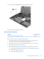
Remove the system board:
1.
Disconnect the following cables from the system board.
(1)
Speaker cable
(2)
Optical drive connector cable
(3)
Display panel cable
(4)
USB board cable
(5)
Power connector cable
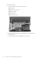
2.
Remove the three Phillips PM2.5×6.0 screws
(1)
that secure the system board to
the base enclosure.
3.
Lift the right side of the system board
(2)
until it rests at an angle.
68
Chapter 4
Removal and replacement procedures