HP 3390 Service Manual - Page 262
To perform other checks, Heating element check, High-voltage contacts check
 |
View all HP 3390 manuals
Add to My Manuals
Save this manual to your list of manuals |
Page 262 highlights
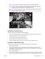
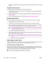
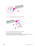
are functioning (image formation and development). Troubleshoot the failure as a transfer or fusing problem. To perform other checks If no image appears on the photosensitive drum, perform these checks: 1. Make sure that you removed the entire length of the sealing tape from the print cartridge before you installed the cartridge. 2. Perform a drum-rotation functional check to ensure that the drum is rotating (see Drum rotation test on page 238). 3. Perform a high-voltage power-supply check. See Heating element check on page 240. Heating element check Media passes between the heating element and a soft pressure roller to fuse toner to the media. 1. Unplug the all-in-one for at least ten minutes. 2. Verify that the thermistor connector is seated into both the all-in-one chassis and the ECU. 3. Remove the heating element connector from the ECU. To measure the continuity of the heating element, measure the resistance between the two pins at the end of the cable. NOTE Normal resistance is 25 ohms +/- 10 ohms for the 110 V all-in-one and 80 ohms +/- 20 ohms for the 220 V all-in-one. If no resistance is measured, replace the fuser. 4. Remove the thermistor connector, and then measure the resistance between J206 pins one and two and between J206 pins three and four. NOTE Normal resistance between both pairs of pins is 370K ohms +/- 50K ohms at 20° C (68°F). 5. If no resistance is measured, replace the fuser. High-voltage contacts check The high-voltage contacts in the all-in-one must have a good connection with the contacts on the print cartridge to provide the necessary voltages for the electrophotographic processes. To check the print-cartridge contacts Remove the print cartridge and visually inspect the three connection points on the ends of the print cartridge: drum ground (callout 1), charging (callout 2), and developing roller (callout 3). If they are dirty or corroded, clean the connection. If they are damaged, replace the print cartridge. NOTE Use only isopropyl alcohol to clean the connections. 240 Chapter 6 Troubleshooting ENWW
-
 1
1 -
2
-
3
-
4
-
5
-
6
-
7
-
8
-
9
-
10
-
11
-
12
-
13
-
14
-
15
-
16
-
17
-
18
-
19
-
20
-
21
-
22
-
23
-
24
-
25
-
26
-
27
-
28
-
29
-
30
-
31
-
32
-
33
-
34
-
35
-
36
-
37
-
38
-
39
-
40
-
41
-
42
-
43
-
44
-
45
-
46
-
47
-
48
-
49
-
50
-
51
-
52
-
53
-
54
-
55
-
56
-
57
-
58
-
59
-
60
-
61
-
62
-
63
-
64
-
65
-
66
-
67
-
68
-
69
-
70
-
71
-
72
-
73
-
74
-
75
-
76
-
77
-
78
-
79
-
80
-
81
-
82
-
83
-
84
-
85
-
86
-
87
-
88
-
89
-
90
-
91
-
92
-
93
-
94
-
95
-
96
-
97
-
98
-
99
-
100
-
101
-
102
-
103
-
104
-
105
-
106
-
107
-
108
-
109
-
110
-
111
-
112
-
113
-
114
-
115
-
116
-
117
-
118
-
119
-
120
-
121
-
122
-
123
-
124
-
125
-
126
-
127
-
128
-
129
-
130
-
131
-
132
-
133
-
134
-
135
-
136
-
137
-
138
-
139
-
140
-
141
-
142
-
143
-
144
-
145
-
146
-
147
-
148
-
149
-
150
-
151
-
152
-
153
-
154
-
155
-
156
-
157
-
158
-
159
-
160
-
161
-
162
-
163
-
164
-
165
-
166
-
167
-
168
-
169
-
170
-
171
-
172
-
173
-
174
-
175
-
176
-
177
-
178
-
179
-
180
-
181
-
182
-
183
-
184
-
185
-
186
-
187
-
188
-
189
-
190
-
191
-
192
-
193
-
194
-
195
-
196
-
197
-
198
-
199
-
200
-
201
-
202
-
203
-
204
-
205
-
206
-
207
-
208
-
209
-
210
-
211
-
212
-
213
-
214
-
215
-
216
-
217
-
218
-
219
-
220
-
221
-
222
-
223
-
224
-
225
-
226
-
227
-
228
-
229
-
230
-
231
-
232
-
233
-
234
-
235
-
236
-
237
-
238
-
239
-
240
-
241
-
242
-
243
-
244
-
245
-
246
-
247
-
248
-
249
-
250
-
251
-
252
-
253
-
254
-
255
-
256
-
 257
257 -
 258
258 -
 259
259 -
 260
260 -
 261
261 -
 262
262 -
 263
263 -
 264
264 -
 265
265 -
 266
266 -
 267
267 -
268
-
269
-
270
-
271
-
272
-
273
-
274
-
275
-
276
-
277
-
278
-
279
-
280
-
281
-
282
-
283
-
284
-
285
-
286
-
287
-
288
-
289
-
290
-
291
-
292
-
293
-
294
-
295
-
296
-
297
-
298
-
299
-
300
-
301
-
302
-
303
-
304
-
305
-
306
-
307
-
308
-
309
-
310
-
311
-
312
-
313
-
314
-
315
-
316
-
317
-
318
-
319
-
320
-
321
-
322
-
323
-
324
-
325
-
326
-
327
-
328
-
329
-
330
-
331
-
332
-
333
-
334
-
335
-
336
-
337
-
338
-
339
-
340
-
341
-
342
-
343
-
344
-
345
-
346
-
347
-
348
-
349
-
350
-
351
-
352
-
353
-
354
-
355
-
356
-
357
-
358
-
359
-
360
-
361
-
362
-
363
-
364
 |
 |