HP A7217A hp 24'' monitor - a7217a, user's guide - Page 17
Troubleshooting, If thin lines appear on your screen (damper wires), On-screen messages, damper wires - problems
 |
UPC - 808736305884
View all HP A7217A manuals
Add to My Manuals
Save this manual to your list of manuals |
Page 17 highlights
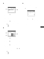
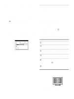
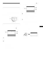
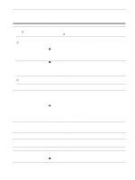
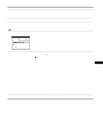
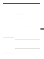
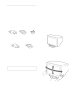
Troubleshooting Before contacting technical support, refer to this section. If thin lines appear on your screen (damper wires) The visible lines on your screen especially when the background screen color is light (usually white), are normal for the Trinitron monitor. This is not a malfunction. These are shadows from the damper wires used to stabilize the aperture grille. The aperture grille is the essential element that makes a Trinitron picture tube unique by allowing more light to reach the screen, resulting in a brighter, more detailed picture. Damper wires On-screen messages If there is something wrong with the input signal, one of the following messages appears on the screen. If NO INPUT SIGNAL appears on line 1 This indicates that no signal is input from the selected connector. I NFORMA T I ON MON I TOR I S WORK I NG I NPUT 1 : NO I NPUT S I GNA L ACT I VA T E BY COMPUT ER CHECK I NPUT SE L ECTOR CHECK WH I T E RED GR E E N B L UE S I GNA L CAB L E 2 The selected connector This message shows the currently selected connector (INPUT 1 or INPUT 2). 3 The remedies One or more of the following messages may appear on the screen. • If ACTIVATE BY COMPUTER appears on the screen, try pressing any key on the computer or moving the mouse, and confirm that your computer's graphic board is completely seated in the correct bus slot. • If CHECK INPUT SELECTOR appears on the screen, try changing the input signal (page 9). • If CHECK SIGNAL CABLE appears on the screen, check that the monitor is correctly connected to the computer (page 6). If OUT OF SCAN RANGE appears on line 1 This indicates that the input signal is not supported by the monitor's specifications. I NFORMA T I ON MON I TOR I S WORK I NG I NPUT 1 : 1 3 0 . 0 kHz / 7 5Hz OUT OF SCAN RANGE CHANGE S I GNA L T I M I NG WH I T E RED GR E E N B L UE 2 The selected connector and the frequencies of the current input signal This message shows the currently selected connector (INPUT 1 or INPUT 2). If the monitor recognizes the frequencies of the current input signal, the horizontal and vertical frequencies are also displayed. 3 The remedies CHANGE SIGNAL TIMING appears on the screen. If you are replacing an old monitor with this monitor, reconnect the old monitor. Then adjust the computer's graphic board so that the horizontal frequency is between 30 - 121 kHz, and the vertical frequency is between 48 - 160 Hz. For more information, see "Trouble symptoms and remedies" on page 18. Displaying this monitor's name, serial number, and date of manufacture. While the monitor is receiving a video signal, press and hold the joystick for more than 5 seconds to display this monitor's information box. b Example INFORMATION MODEL : A7217A SER NO : 1234567 MANUFACTURED : 2001-52 GB If the problem persists, call your service representative and give the following information. • Model name: A7217A • Serial number • Name and specifications of your computer and graphic board. 17
-
 1
1 -
2
-
3
-
4
-
5
-
6
-
7
-
8
-
9
-
10
-
11
-
 12
12 -
 13
13 -
 14
14 -
 15
15 -
 16
16 -
 17
17 -
 18
18 -
 19
19 -
 20
20 -
 21
21 -
 22
22 -
23
-
24
-
25
-
26
-
27
-
28
-
29
-
30
-
31
-
32
-
33
-
34
-
35
-
36
-
37
-
38
-
39
-
40
-
41
-
42
-
43
-
44
-
45
-
46
-
47
-
48
-
49
-
50
-
51
-
52
-
53
-
54
-
55
-
56
-
57
-
58
-
59
-
60
-
61
-
62
-
63
-
64
-
65
-
66
-
67
-
68
-
69
-
70
-
71
-
72
-
73
-
74
-
75
-
76
-
77
-
78
-
79
-
80
-
81
-
82
-
83
-
84
-
85
-
86
-
87
-
88
-
89
-
90
-
91
-
92
-
93
-
94
-
95
-
96
-
97
-
98
-
99
-
100
-
101
-
102
-
103
-
104
-
105
-
106
-
107
-
108
-
109
-
110
-
111
-
112
-
113
-
114
-
115
-
116
-
117
-
118
-
119
-
120
-
121
-
122
-
123
-
124
-
125
-
126
-
127
-
128
-
129
-
130
-
131
-
132
 |
 |
