HP AE370A HP StorageWorks Fabric OS 6.2 administrator guide (5697-0016, May 20 - Page 178
Logical Switches and connected devices
 |
UPC - 882780362611
View all HP AE370A manuals
Add to My Manuals
Save this manual to your list of manuals |
Page 178 highlights
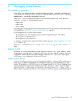
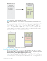
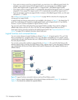
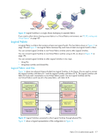
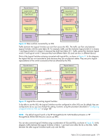
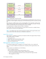
• If you want to remove a port from a Logical Switch, you must move it to a different Logical Switch. For example, if you want to remove P4 from logical switch 3, you must assign it to a different Logical Switch, either logical switch 2, logical switch 4, or logical switch 1 (the default Logical Switch). • If you assign a port to a Logical Switch, it is automatically removed from the Logical Switch it is currently assigned to. If you assign P3 to logical switch 3, P3 is automatically removed from logical switch 2. • If you do not assign a port to any Logical Switch, it remains in the default Logical Switch, as is the case with ports 0, 1, 7, and 8. See "Adding and removing ports on a Logical Switch" on page 186 for instructions for assigning and moving ports on Logical Switch. A Logical Switch can have as many ports as are available in the chassis. In Figure 11, the chassis has 10 ports. You could assign all 10 ports to a single Logical Switch, such as logical switch 2; if you did this, however, no ports would be available for logical switches 3 and 4. You can move only F_Ports and E_Ports from one Logical Switch to another. If you want to configure a different type of port, such as a VE_Port or EX_Port, you must configure the port after you move it. Some types of ports cannot be moved from the default Logical Switch. See "Supported platforms for Virtual Fabrics" on page 181 for detailed information about these ports. Logical Switches and connected devices You can connect devices to Logical Switches, as shown in Figure 12. In logical switch 2, P2 is an F_Port that is connected to H1. In logical switch 3, P4 is an F_Port that is connected to D1. H1 and D1 cannot communicate with each other because they are in different fabrics, even though they are both connected to the same physical chassis. You can also connect other switches to Logical Switches. In Figure 12, P6 is an E_Port that forms an ISL between logical switch 4 and the non-Virtual Fabrics switch. Logical switch 4 is the only Logical Switch that can communicate with the non-Virtual Fabrics switch and D2, because the other Logical Switches are in different fabrics. Physical chassis Logical switch 1 P1 (Default logical switch) Fabric ID 128 H1 Logical switch 2 P2 Fabric ID 1 P3 D1 P4 Logical switch 3 Fabric ID 15 P5 D2 Logical switch 4 P6 ISL Fabric ID 8 Switch Figure 12 Logical Switches connected to devices and non-Virtual Fabrics switch Figure 13 shows a logical representation of the physical chassis and devices in Figure 12. As shown in Figure 13, the devices are isolated into separate fabrics. 176 Managing virtual fabrics
-
 1
1 -
2
-
3
-
4
-
5
-
6
-
7
-
8
-
9
-
10
-
11
-
12
-
13
-
14
-
15
-
16
-
17
-
18
-
19
-
20
-
21
-
22
-
23
-
24
-
25
-
26
-
27
-
28
-
29
-
30
-
31
-
32
-
33
-
34
-
35
-
36
-
37
-
38
-
39
-
40
-
41
-
42
-
43
-
44
-
45
-
46
-
47
-
48
-
49
-
50
-
51
-
52
-
53
-
54
-
55
-
56
-
57
-
58
-
59
-
60
-
61
-
62
-
63
-
64
-
65
-
66
-
67
-
68
-
69
-
70
-
71
-
72
-
73
-
74
-
75
-
76
-
77
-
78
-
79
-
80
-
81
-
82
-
83
-
84
-
85
-
86
-
87
-
88
-
89
-
90
-
91
-
92
-
93
-
94
-
95
-
96
-
97
-
98
-
99
-
100
-
101
-
102
-
103
-
104
-
105
-
106
-
107
-
108
-
109
-
110
-
111
-
112
-
113
-
114
-
115
-
116
-
117
-
118
-
119
-
120
-
121
-
122
-
123
-
124
-
125
-
126
-
127
-
128
-
129
-
130
-
131
-
132
-
133
-
134
-
135
-
136
-
137
-
138
-
139
-
140
-
141
-
142
-
143
-
144
-
145
-
146
-
147
-
148
-
149
-
150
-
151
-
152
-
153
-
154
-
155
-
156
-
157
-
158
-
159
-
160
-
161
-
162
-
163
-
164
-
165
-
166
-
167
-
168
-
169
-
170
-
171
-
172
-
 173
173 -
 174
174 -
 175
175 -
 176
176 -
 177
177 -
 178
178 -
 179
179 -
 180
180 -
 181
181 -
 182
182 -
 183
183 -
184
-
185
-
186
-
187
-
188
-
189
-
190
-
191
-
192
-
193
-
194
-
195
-
196
-
197
-
198
-
199
-
200
-
201
-
202
-
203
-
204
-
205
-
206
-
207
-
208
-
209
-
210
-
211
-
212
-
213
-
214
-
215
-
216
-
217
-
218
-
219
-
220
-
221
-
222
-
223
-
224
-
225
-
226
-
227
-
228
-
229
-
230
-
231
-
232
-
233
-
234
-
235
-
236
-
237
-
238
-
239
-
240
-
241
-
242
-
243
-
244
-
245
-
246
-
247
-
248
-
249
-
250
-
251
-
252
-
253
-
254
-
255
-
256
-
257
-
258
-
259
-
260
-
261
-
262
-
263
-
264
-
265
-
266
-
267
-
268
-
269
-
270
-
271
-
272
-
273
-
274
-
275
-
276
-
277
-
278
-
279
-
280
-
281
-
282
-
283
-
284
-
285
-
286
-
287
-
288
-
289
-
290
-
291
-
292
-
293
-
294
-
295
-
296
-
297
-
298
-
299
-
300
-
301
-
302
-
303
-
304
-
305
-
306
-
307
-
308
-
309
-
310
-
311
-
312
-
313
-
314
-
315
-
316
-
317
-
318
-
319
-
320
-
321
-
322
-
323
-
324
-
325
-
326
-
327
-
328
-
329
-
330
-
331
-
332
-
333
-
334
-
335
-
336
-
337
-
338
-
339
-
340
-
341
-
342
-
343
-
344
-
345
-
346
-
347
-
348
-
349
-
350
-
351
-
352
-
353
-
354
-
355
-
356
-
357
-
358
-
359
-
360
-
361
-
362
-
363
-
364
-
365
-
366
-
367
-
368
-
369
-
370
-
371
-
372
-
373
-
374
-
375
-
376
-
377
-
378
-
379
-
380
-
381
-
382
-
383
-
384
-
385
-
386
-
387
-
388
-
389
-
390
-
391
-
392
-
393
-
394
-
395
-
396
-
397
-
398
-
399
-
400
-
401
-
402
-
403
-
404
-
405
-
406
-
407
-
408
-
409
-
410
-
411
-
412
-
413
-
414
-
415
-
416
-
417
-
418
-
419
-
420
-
421
-
422
-
423
-
424
-
425
-
426
-
427
-
428
-
429
-
430
-
431
-
432
-
433
-
434
-
435
-
436
-
437
-
438
-
439
-
440
-
441
-
442
-
443
-
444
-
445
-
446
-
447
-
448
-
449
-
450
-
451
-
452
-
453
-
454
-
455
-
456
-
457
-
458
-
459
-
460
-
461
-
462
-
463
-
464
-
465
-
466
-
467
-
468
-
469
-
470
-
471
-
472
-
473
-
474
-
475
-
476
-
477
-
478
-
479
-
480
-
481
-
482
-
483
-
484
-
485
-
486
-
487
-
488
-
489
-
490
-
491
-
492
-
493
-
494
-
495
-
496
-
497
-
498
-
499
-
500
-
501
-
502
-
503
-
504
-
505
-
506
-
507
-
508
-
509
-
510
-
511
-
512
-
513
-
514
-
515
-
516
-
517
-
518
-
519
-
520
-
521
-
522
-
523
-
524
-
525
-
526
-
527
-
528
-
529
-
530
-
531
-
532
-
533
-
534
-
535
-
536
-
537
-
538
-
539
-
540
-
541
-
542
-
543
-
544
-
545
-
546
-
547
-
548
-
549
-
550
-
551
-
552
-
553
-
554
-
555
-
556
-
557
-
558
-
559
-
560
-
561
-
562
-
563
-
564
-
565
-
566
-
567
-
568
-
569
-
570
-
571
-
572
-
573
-
574
-
575
-
576
 |
 |
