HP Chromebook 11-1100 Maintenance and Service Guide 1 - Page 52
Memory modules see, WLAN module see
 |
View all HP Chromebook 11-1100 manuals
Add to My Manuals
Save this manual to your list of manuals |
Page 52 highlights
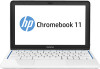
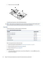
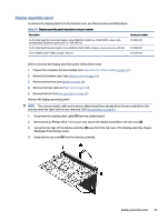
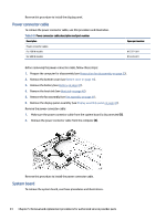
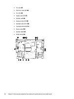
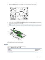
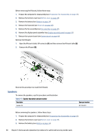
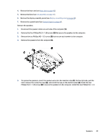
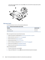
Table 5-10 System board descriptions and part numbers Description System board (includes processor): All system boards use the following part numbers: xxxxxx-001: Non-Windows operating system xxxxxx-601: Windows 10 operating system Intel Core i9-12900H, RTX 3060, 6 GB Intel Core i9-12900H, RTX 3060, for OLED, 6 GB Intel Core i7-12700H, RTX 3060, for OLED, 6 GB Intel Core i7-12700H, Arc A370M, for OLED, 4 GB Intel Core i7-12700H, RTX 3060, 6 GB Intel Core i7-12700H, Arc A370M, 4 GB Intel Core 15-12500H, Arc A370M, 4 GB Spare part number N12357-601 N14910-601 N14909-601 N14908-601 N12356-601 N12355-601 N12354-601 Before removing the system board, follow these steps: 1. Prepare the computer for disassembly (see Preparation for disassembly on page 33). 2. Remove the bottom cover (see Bottom cover on page 33). 3. Remove the battery (see Battery on page 34). 4. Remove the heat sink (see Heat sink on page 40). 5. Remove the fans (see Fan assembly on page 41). When you replace the system board, be sure to remove the following components (as applicable) from the defective system board and install them on the replacement system board: ● Memory modules (see Memory modules on page 35). ● WLAN module (see WLAN module on page 37). ● Display assembly panel (see Display assembly panel on page 43). IMPORTANT: After replacing the system board or the display panel assembly, it is necessary to run the service tool to have the new ambient light sensor (ALS) data written to the system BIOS. Please search for the related advisory for more information. Remove the system board: 1. Identify the following cables, and make sure they have been disconnected from the system board: ● Webcam cable (1) ● Power connector cable (2) ● IR board cable (ZIF) (3) System board 45
-
 1
1 -
2
-
3
-
4
-
5
-
6
-
7
-
8
-
9
-
10
-
11
-
12
-
13
-
14
-
15
-
16
-
17
-
18
-
19
-
20
-
21
-
22
-
23
-
24
-
25
-
26
-
27
-
28
-
29
-
30
-
31
-
32
-
33
-
34
-
35
-
36
-
37
-
38
-
39
-
40
-
41
-
42
-
43
-
44
-
45
-
46
-
 47
47 -
 48
48 -
 49
49 -
 50
50 -
 51
51 -
 52
52 -
 53
53 -
 54
54 -
 55
55 -
 56
56 -
 57
57 -
58
-
59
-
60
-
61
-
62
-
63
-
64
-
65
-
66
-
67
-
68
-
69
-
70
-
71
-
72
-
73
-
74
-
75
-
76
-
77
-
78
-
79
-
80
-
81
-
82
-
83
-
84
-
85
-
86
-
87
-
88
-
89
-
90
 |
 |