HP Chromebook 11-ae000 Maintenance and Service Guide - Page 39
System board, the computer on, and then shut it down through the operating system.
 |
View all HP Chromebook 11-ae000 manuals
Add to My Manuals
Save this manual to your list of manuals |
Page 39 highlights
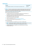
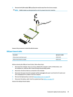
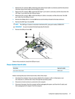
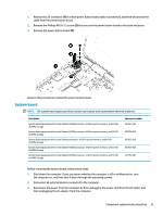
1. Release the ZIF connector (1) to which power button board cable is connected, and then disconnect the cable from the power button board. 2. Remove the Phillips M2.0×3.5 screw (2) that secures the power button board to the base enclosure. 3. Remove the power button board (3). Reverse this procedure to install the power button board. System board NOTE: All system board spare part kits include a processor and replacement thermal material. Description System board equipped with an Intel Celeron N3350 processor, 8-GB of system memory, and 64-GB of eMMC storage System board equipped with an Intel Celeron N3350 processor, 8-GB of system memory, and 32-GB of eMMC storage System board equipped with an Intel Celeron processor, 4-GB of system memory, and 64-GB of eMMC storage System board equipped with an Intel Celeron N3350 processor, 4-GB of system memory, and 32-GB of eMMC storage System board equipped with an Intel Celeron N3350 processor, 4-GB of system memory, and 16-GB of eMMC storage Spare part number 927657-001 927656-001 927655-001 927654-001 L01750-001 Before removing the system board, follow these steps: 1. Shut down the computer. If you are unsure whether the computer is off or in Hibernation, turn the computer on, and then shut it down through the operating system. 2. Disconnect all external devices connected to the computer. 3. Disconnect the power from the computer by first unplugging the power cord from the AC outlet, and then unplugging the AC adapter from the computer. Component replacement procedures 33
-
 1
1 -
2
-
3
-
4
-
5
-
6
-
7
-
8
-
9
-
10
-
11
-
12
-
13
-
14
-
15
-
16
-
17
-
18
-
19
-
20
-
21
-
22
-
23
-
24
-
25
-
26
-
27
-
28
-
29
-
30
-
31
-
32
-
33
-
 34
34 -
 35
35 -
 36
36 -
 37
37 -
 38
38 -
 39
39 -
 40
40 -
 41
41 -
 42
42 -
 43
43 -
 44
44 -
45
-
46
-
47
-
48
-
49
-
50
-
51
-
52
-
53
-
54
-
55
-
56
-
57
-
58
-
59
-
60
-
61
 |
 |
