HP Chromebook 11-ae000 Maintenance and Service Guide - Page 44
Display assembly, from the terminals on the WLAN module.
 |
View all HP Chromebook 11-ae000 manuals
Add to My Manuals
Save this manual to your list of manuals |
Page 44 highlights
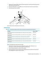
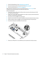
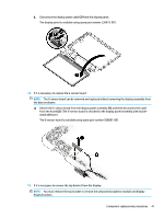
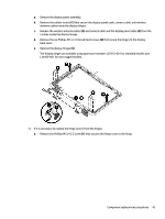
Display assembly NOTE: The display assembly is spared at the subcomponent level. For display assembly spare part information, see the individual removal subsections. Before removing the display assembly, follow these steps: 1. Shut down the computer. If you are unsure whether the computer is off or in Hibernation, turn the computer on, and then shut it down through the operating system. 2. Disconnect all external devices connected to the computer. 3. Disconnect the power from the computer by first unplugging the power cord from the AC outlet, and then unplugging the AC adapter from the computer. 4. Remove the keyboard/top cover (see Keyboard/top cover on page 18). 5. Disconnect the battery cable from the system board (see Battery on page 26). Remove the display assembly: 1. Release the ZIF connector (1) to which power button board cable is connected, and then disconnect the power button board cable from the USB port board. 2. Detach the power button board cable (2) from the display hinge. (The power button board cable is attached to the display hinge with double-sided adhesive.) 3. Disconnect the WLAN antenna cables (3) from the terminals on the WLAN module. NOTE: The WLAN antenna cable labeled "1/MAIN" connects to the WLAN module "Main" terminal. The WLAN antenna cable labeled "2/AUX" connects to the WLAN module "Aux" terminal. 4. Disconnect the camera cable (4) from the system board. 5. Release the camera cable from the retention clips (5) and routing channel built into the base enclosure. 6. Release the adhesive support strip (6) the secures the display panel cable to the system board. 7. Disconnect the display panel cable (7) from the system board. 38 Chapter 5 Removal and replacement procedures
-
 1
1 -
2
-
3
-
4
-
5
-
6
-
7
-
8
-
9
-
10
-
11
-
12
-
13
-
14
-
15
-
16
-
17
-
18
-
19
-
20
-
21
-
22
-
23
-
24
-
25
-
26
-
27
-
28
-
29
-
30
-
31
-
32
-
33
-
34
-
35
-
36
-
37
-
38
-
 39
39 -
 40
40 -
 41
41 -
 42
42 -
 43
43 -
 44
44 -
 45
45 -
 46
46 -
 47
47 -
 48
48 -
 49
49 -
50
-
51
-
52
-
53
-
54
-
55
-
56
-
57
-
58
-
59
-
60
-
61
 |
 |
