HP Chromebook 11-ae000 Maintenance and Service Guide - Page 46
Swing the top edge of the display panel
 |
View all HP Chromebook 11-ae000 manuals
Add to My Manuals
Save this manual to your list of manuals |
Page 46 highlights
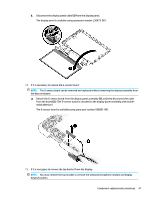
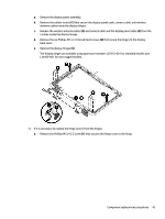
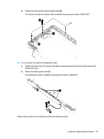
a. Release the top edge of the display bezel (1) from the display assembly. b. Release the left and right edges of the display bezel (2) from the display assembly. c. Release the bottom edge of the display bezel (3) from the display assembly. d. Remove the display bezel (4) from the display assembly. The display bezel is available using spare part number L36467-001. 13. If it is necessary to replace the display panel: a. Remove the four Phillips M2.0×2.5 screws that secure the display panel to the display back cover. b. Swing the top edge of the display panel (1) up and forward until the panel rests upside down next to the display enclosure. c. Release the adhesive support strip (2) that secures the display panel cable connector to the display panel. 40 Chapter 5 Removal and replacement procedures
-
 1
1 -
2
-
3
-
4
-
5
-
6
-
7
-
8
-
9
-
10
-
11
-
12
-
13
-
14
-
15
-
16
-
17
-
18
-
19
-
20
-
21
-
22
-
23
-
24
-
25
-
26
-
27
-
28
-
29
-
30
-
31
-
32
-
33
-
34
-
35
-
36
-
37
-
38
-
39
-
40
-
 41
41 -
 42
42 -
 43
43 -
 44
44 -
 45
45 -
 46
46 -
 47
47 -
 48
48 -
 49
49 -
 50
50 -
 51
51 -
52
-
53
-
54
-
55
-
56
-
57
-
58
-
59
-
60
-
61
 |
 |
