HP Chromebook 11-ae000 Maintenance and Service Guide - Page 40
and routing channel built into the base enclosure
 |
View all HP Chromebook 11-ae000 manuals
Add to My Manuals
Save this manual to your list of manuals |
Page 40 highlights
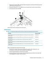
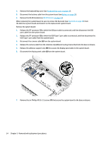
4. Remove the keyboard/top cover (see Keyboard/top cover on page 18). 5. Disconnect the battery cable from the system board (see Battery on page 26). 6. Remove the WLAN module (see WLAN module on page 28). When replacing the system board, be sure to remove the heat sink (see Heat sink on page 36) from the defective system board and install it on the replacement system board. Remove the system board: 1. Release the ZIF connector (1) to which the USB port cable is connected, and then disconnect the USB port cable from the system board 2. Release the ZIF connector (2) to which the USB Type-C port cable is connected, and then disconnect the USB Type-C port cable from the system board. 3. Disconnect the camera cable (3) from the system board. 4. Release the camera cable from the retention clips (4) and routing channel built into the base enclosure. 5. Release the adhesive support strip (5) the secures the display panel cable to the system board. 6. Disconnect the display panel cable (6) from the system board. 7. Remove the six Phillips M2.0×3.5 screws (1) that secure the system board to the base enclosure. 34 Chapter 5 Removal and replacement procedures
-
 1
1 -
2
-
3
-
4
-
5
-
6
-
7
-
8
-
9
-
10
-
11
-
12
-
13
-
14
-
15
-
16
-
17
-
18
-
19
-
20
-
21
-
22
-
23
-
24
-
25
-
26
-
27
-
28
-
29
-
30
-
31
-
32
-
33
-
34
-
 35
35 -
 36
36 -
 37
37 -
 38
38 -
 39
39 -
 40
40 -
 41
41 -
 42
42 -
 43
43 -
 44
44 -
 45
45 -
46
-
47
-
48
-
49
-
50
-
51
-
52
-
53
-
54
-
55
-
56
-
57
-
58
-
59
-
60
-
61
 |
 |
