HP ENVY 13-d000 Maintenance and Service Guide - Page 46
Power connector cable
 |
View all HP ENVY 13-d000 manuals
Add to My Manuals
Save this manual to your list of manuals |
Page 46 highlights
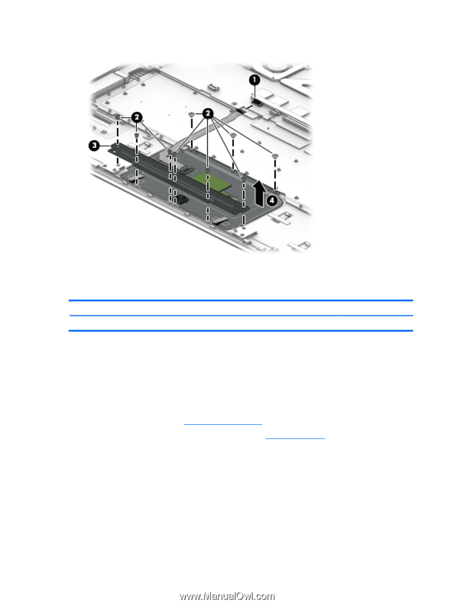
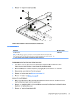
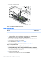
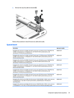
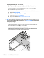
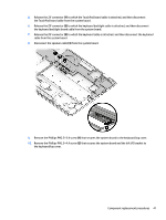
4. Remove the TouchPad board (4). Reverse this procedure to install the TouchPad board. Power connector cable Description Power connector cable Spare part number 838841-001 Before removing the power connector cable, follow these steps: 1. Turn off the computer. If you are unsure whether the computer is off or in Hibernation, turn the computer on, and then shut it down through the operating system. 2. Disconnect the power from the computer by unplugging the power cord from the computer. 3. Disconnect all external devices from the computer. 4. Remove the bottom cover (see Bottom cover on page 26). 5. Disconnect the battery cable from the system board (see Battery on page 28). Remove the power connector cable: 1. Disconnect the power connector cable (1) from the system board. 2. Release the power connector cable (2) from the routing channel built into the system board. 3. Remove the two Phillips PM2.0×4.4 screws (3) that secure the power connector cable and power connector cable bracket to the keyboard/top cover. 4. Remove the right I/O bracket (4). The right I/O bracket is available using spare part number 829299-001. 36 Chapter 5 Removal and replacement procedures
-
 1
1 -
2
-
3
-
4
-
5
-
6
-
7
-
8
-
9
-
10
-
11
-
12
-
13
-
14
-
15
-
16
-
17
-
18
-
19
-
20
-
21
-
22
-
23
-
24
-
25
-
26
-
27
-
28
-
29
-
30
-
31
-
32
-
33
-
34
-
35
-
36
-
37
-
38
-
39
-
40
-
 41
41 -
 42
42 -
 43
43 -
 44
44 -
 45
45 -
 46
46 -
 47
47 -
 48
48 -
 49
49 -
 50
50 -
 51
51 -
52
-
53
-
54
-
55
-
56
-
57
-
58
-
59
-
60
-
61
-
62
-
63
-
64
-
65
-
66
-
67
-
68
-
69
-
70
-
71
-
72
-
73
-
74
-
75
-
76
-
77
-
78
-
79
-
80
-
81
-
82
 |
 |