HP ENVY 13-d000 Maintenance and Service Guide - Page 63
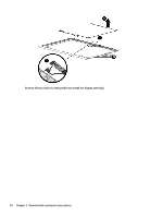
from the webcam/microphone module., Release the display panel cable from the retention clips
 |
View all HP ENVY 13-d000 manuals
Add to My Manuals
Save this manual to your list of manuals |
Page 63 highlights
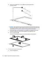
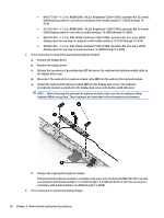
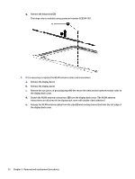
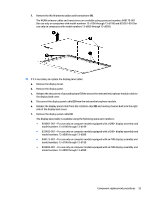
f. Remove the WLAN antenna cables and transceivers (4). The WLAN antenna cables and transceivers are available using spare part numbers 848170-001 (for use only on computers with model numbers 13-d100 through 13-d199) and 829287-001 (for use only on computers with model numbers 13-d000 through 13-d099). 10. If it is necessary to replace the display panel cable: a. Remove the display bezel. b. Remove the display panel. c. Release the two pieces of grounding tape (1) the secure the webcam/microphone module cable to the display back cover. d. Disconnect the display panel cable (2) from the webcam/microphone module. e. Release the display panel cable from the retention clips (3) and routing channel built into the right side of the display back cover. f. Remove the display panel cable (4). The display panel cable is available using the following spare part numbers: ● 854981-001 - For use only on computer models equipped with a QHD+ display assembly and model numbers 13-d100 through 13-d199 ● 833483-001 - For use only on computer models equipped with a QHD+ display assembly and model numbers 13-d000 through 13-d099 ● 848175-001 - For use only on computer models equipped with an FHD display assembly and model numbers 13-d100 through 13-d199 ● 833482-001 - For use only on computer models equipped with an FHD display assembly and model numbers 13-d000 through 13-d099 Component replacement procedures 53
-
 1
1 -
2
-
3
-
4
-
5
-
6
-
7
-
8
-
9
-
10
-
11
-
12
-
13
-
14
-
15
-
16
-
17
-
18
-
19
-
20
-
21
-
22
-
23
-
24
-
25
-
26
-
27
-
28
-
29
-
30
-
31
-
32
-
33
-
34
-
35
-
36
-
37
-
38
-
39
-
40
-
41
-
42
-
43
-
44
-
45
-
46
-
47
-
48
-
49
-
50
-
51
-
52
-
53
-
54
-
55
-
56
-
57
-
 58
58 -
 59
59 -
 60
60 -
 61
61 -
 62
62 -
 63
63 -
 64
64 -
 65
65 -
 66
66 -
 67
67 -
 68
68 -
69
-
70
-
71
-
72
-
73
-
74
-
75
-
76
-
77
-
78
-
79
-
80
-
81
-
82
 |
 |
