HP ENVY 13-d000 Maintenance and Service Guide - Page 59
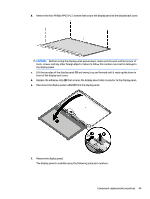
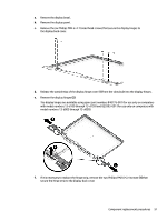
that secures the display panel cable connector to the display panel., Release the adhesive strip
 |
View all HP ENVY 13-d000 manuals
Add to My Manuals
Save this manual to your list of manuals |
Page 59 highlights
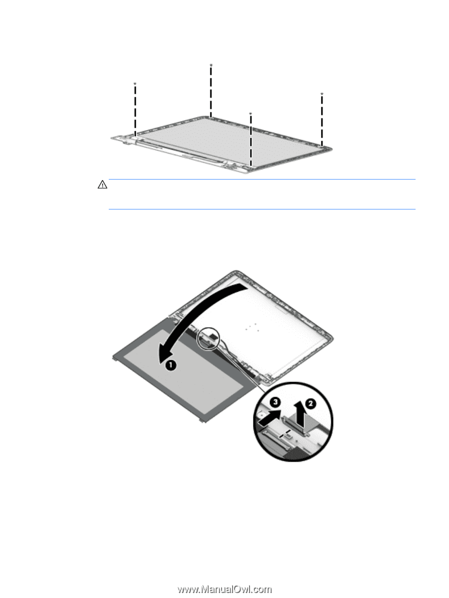
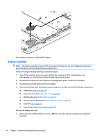
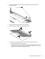
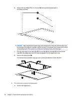
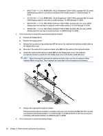
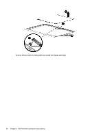
b. Remove the four Phillips PM2.0×2.3 screws that secure the display panel to the display back cover. CAUTION: Before turning the display panel upside down, make sure the work surface is clear of tools, screws, and any other foreign objects. Failure to follow this caution can result in damage to the display panel. c. Lift the top edge of the display panel (1) and swing it up and forward until it rests upside down in front of the display back cover. d. Release the adhesive strip (2) that secures the display panel cable connector to the display panel. e. Disconnect the display panel cable (3) from the display panel. f. Remove the display panel. The display panel is available using the following spare part numbers: Component replacement procedures 49
-
 1
1 -
2
-
3
-
4
-
5
-
6
-
7
-
8
-
9
-
10
-
11
-
12
-
13
-
14
-
15
-
16
-
17
-
18
-
19
-
20
-
21
-
22
-
23
-
24
-
25
-
26
-
27
-
28
-
29
-
30
-
31
-
32
-
33
-
34
-
35
-
36
-
37
-
38
-
39
-
40
-
41
-
42
-
43
-
44
-
45
-
46
-
47
-
48
-
49
-
50
-
51
-
52
-
53
-
 54
54 -
 55
55 -
 56
56 -
 57
57 -
 58
58 -
 59
59 -
 60
60 -
 61
61 -
 62
62 -
 63
63 -
 64
64 -
65
-
66
-
67
-
68
-
69
-
70
-
71
-
72
-
73
-
74
-
75
-
76
-
77
-
78
-
79
-
80
-
81
-
82
 |
 |