HP ENVY 13-d000 Maintenance and Service Guide - Page 56
Display assembly
 |
View all HP ENVY 13-d000 manuals
Add to My Manuals
Save this manual to your list of manuals |
Page 56 highlights
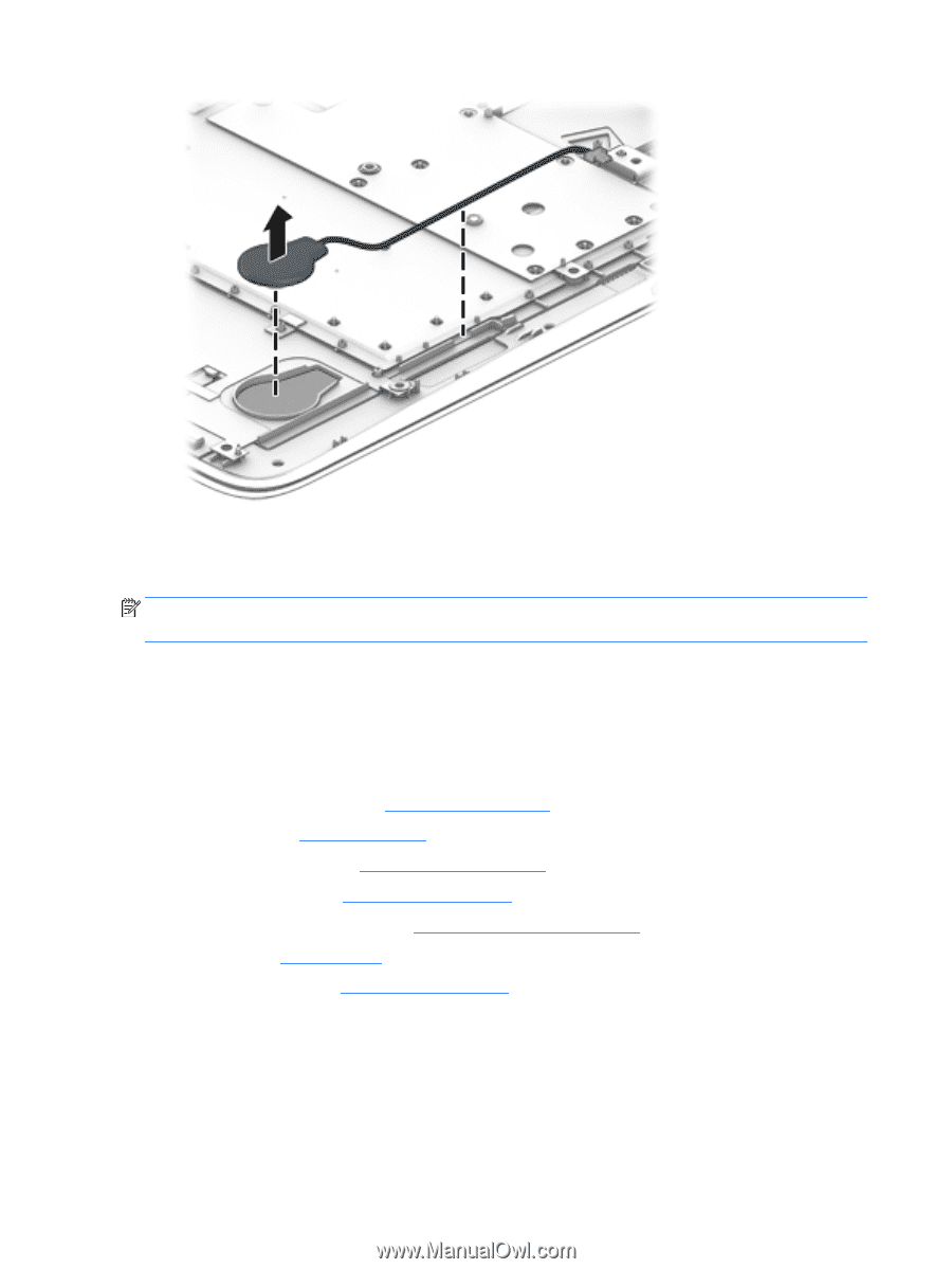
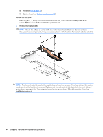
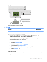
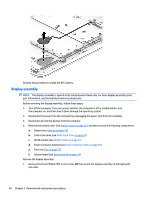
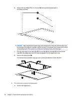
Reverse this procedure to install the RTC battery. Display assembly NOTE: The display assembly is spared at the subcomponent level only. For more display assembly spare part information, see the individual removal subsections. Before removing the display assembly, follow these steps: 1. Turn off the computer. If you are unsure whether the computer is off or in Hibernation, turn the computer on, and then shut it down through the operating system. 2. Disconnect the power from the computer by unplugging the power cord from the computer. 3. Disconnect all external devices from the computer. 4. Remove the bottom cover (see Bottom cover on page 26), and then remove the following components: a. Battery (see Battery on page 28) b. Solid-state drive (see Solid-state drive on page 29) c. WLAN module (see WLAN module on page 31) d. Power connector bracket (see Power connector cable on page 36) e. Fans (see Fan on page 37) f. System board (see System board on page 39) Remove the display assembly: 1. Remove the three Phillips PM2.5×4.4 screws (1) that secure the display assembly to the keyboard/ top cover. 46 Chapter 5 Removal and replacement procedures
-
 1
1 -
2
-
3
-
4
-
5
-
6
-
7
-
8
-
9
-
10
-
11
-
12
-
13
-
14
-
15
-
16
-
17
-
18
-
19
-
20
-
21
-
22
-
23
-
24
-
25
-
26
-
27
-
28
-
29
-
30
-
31
-
32
-
33
-
34
-
35
-
36
-
37
-
38
-
39
-
40
-
41
-
42
-
43
-
44
-
45
-
46
-
47
-
48
-
49
-
50
-
 51
51 -
 52
52 -
 53
53 -
 54
54 -
 55
55 -
 56
56 -
 57
57 -
 58
58 -
 59
59 -
 60
60 -
 61
61 -
62
-
63
-
64
-
65
-
66
-
67
-
68
-
69
-
70
-
71
-
72
-
73
-
74
-
75
-
76
-
77
-
78
-
79
-
80
-
81
-
82
 |
 |