HP ENVY 13-d100 Maintenance and Service Guide - Page 36
Removal and replacement procedures, Bottom cover
 |
View all HP ENVY 13-d100 manuals
Add to My Manuals
Save this manual to your list of manuals |
Page 36 highlights
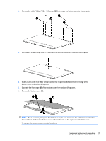
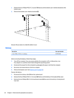
5 Removal and replacement procedures CAUTION: Components described in this chapter should only be accessed by an authorized service provider. Accessing these parts can damage the computer or void the warranty. Component replacement procedures NOTE: Details about the computer, including model, serial number, product key, and length of warranty, are on the service tag one the bottom of the computer. See Bottom on page 11 for details. There are as many as 61 screws that must be removed, replaced, and/or loosened when servicing the computer. Make special note of each screw size and location during removal and replacement. Bottom cover NOTE: The bottom cover spare part kit includes two rear rubber feet, one front rubber foot, speaker grilles, shielding, and retention brackets. Description Bottom cover (includes two rear rubber feet, one front rubber foot, speaker grilles, shielding, and retention brackets) Spare part number 829289-001 and 848658-001 Before disassembling the computer, follow these steps: 1. Turn off the computer. If you are unsure whether the computer is off or in Hibernation, turn the computer on, and then shut it down through the operating system. 2. Disconnect the power from the computer by unplugging the power cord from the computer. 3. Disconnect all external devices from the computer. Remove the bottom cover: 1. Remove the bottom cover rear rubber feet (1). The bottom cover rear rubber feet are available using spare part number 829307-001. 26 Chapter 5 Removal and replacement procedures
-
 1
1 -
2
-
3
-
4
-
5
-
6
-
7
-
8
-
9
-
10
-
11
-
12
-
13
-
14
-
15
-
16
-
17
-
18
-
19
-
20
-
21
-
22
-
23
-
24
-
25
-
26
-
27
-
28
-
29
-
30
-
 31
31 -
 32
32 -
 33
33 -
 34
34 -
 35
35 -
 36
36 -
 37
37 -
 38
38 -
 39
39 -
 40
40 -
 41
41 -
42
-
43
-
44
-
45
-
46
-
47
-
48
-
49
-
50
-
51
-
52
-
53
-
54
-
55
-
56
-
57
-
58
-
59
-
60
-
61
-
62
-
63
-
64
-
65
-
66
-
67
-
68
-
69
-
70
-
71
-
72
-
73
-
74
-
75
-
76
-
77
-
78
-
79
-
80
-
81
-
82
 |
 |