HP ENVY 13-d100 Maintenance and Service Guide - Page 51
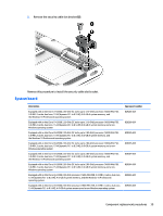
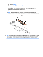
Remove the Phillips PM2.5×3.4 screw, that secures the system board to the keyboard/top cover.
 |
View all HP ENVY 13-d100 manuals
Add to My Manuals
Save this manual to your list of manuals |
Page 51 highlights
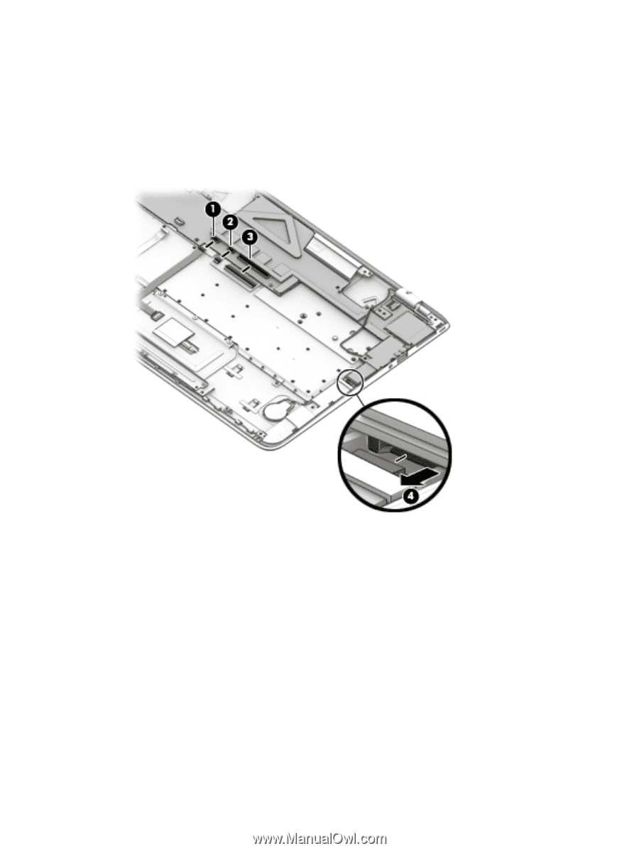
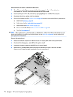
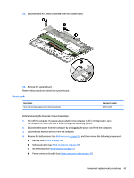
5. Release the ZIF connector (1) to which the TouchPad board cable is attached, and then disconnect the TouchPad board cable from the system board. 6. Release the ZIF connector (2) to which the keyboard backlight cable is attached, and then disconnect the keyboard backlight board cable from the system board. 7. Release the ZIF connector (3) to which the keyboard cable is attached, and then disconnect the keyboard cable from the system board. 8. Disconnect the speaker cable (4) from the system board. 9. Remove the Phillips PM2.5×3.4 screw (1) that secures the system board to the keyboard/top cover. 10. Remove the Phillips PM2.5×4.4 screw (2) that secures the system board and the left I/O bracket to the keyboard/top cover. Component replacement procedures 41
-
 1
1 -
2
-
3
-
4
-
5
-
6
-
7
-
8
-
9
-
10
-
11
-
12
-
13
-
14
-
15
-
16
-
17
-
18
-
19
-
20
-
21
-
22
-
23
-
24
-
25
-
26
-
27
-
28
-
29
-
30
-
31
-
32
-
33
-
34
-
35
-
36
-
37
-
38
-
39
-
40
-
41
-
42
-
43
-
44
-
45
-
 46
46 -
 47
47 -
 48
48 -
 49
49 -
 50
50 -
 51
51 -
 52
52 -
 53
53 -
 54
54 -
 55
55 -
 56
56 -
57
-
58
-
59
-
60
-
61
-
62
-
63
-
64
-
65
-
66
-
67
-
68
-
69
-
70
-
71
-
72
-
73
-
74
-
75
-
76
-
77
-
78
-
79
-
80
-
81
-
82
 |
 |