HP ENVY 13-d100 Maintenance and Service Guide - Page 55
RTC battery, Power connector bracket see
 |
View all HP ENVY 13-d100 manuals
Add to My Manuals
Save this manual to your list of manuals |
Page 55 highlights
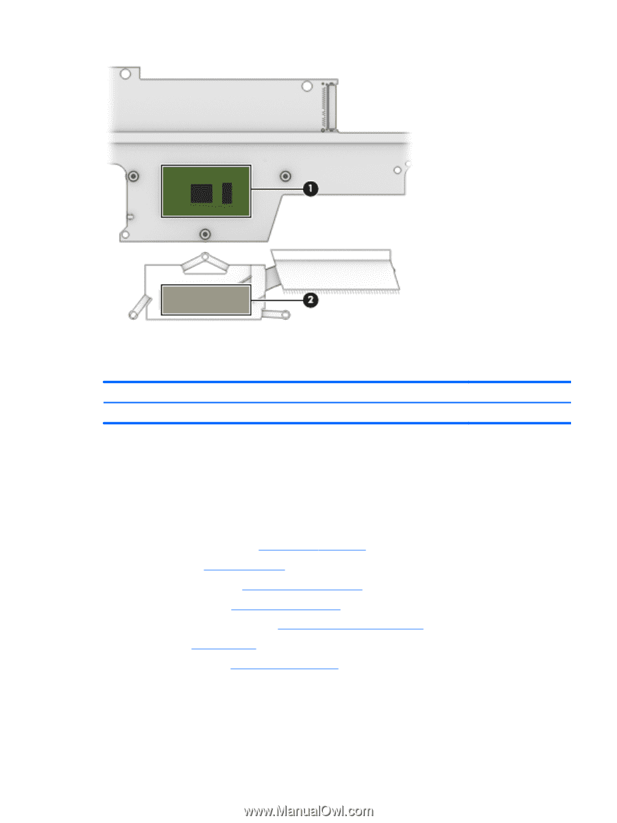
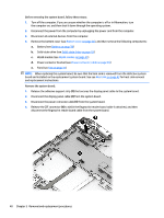
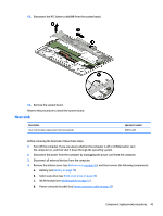
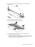
Reverse this procedure to install the heat sink. RTC battery Description RTC battery (includes cable and double-sided adhesive) Spare part number 829306-001 Before removing the RTC battery, follow these steps: 1. Turn off the computer. If you are unsure whether the computer is off or in Hibernation, turn the computer on, and then shut it down through the operating system. 2. Disconnect the power from the computer by unplugging the power cord from the computer. 3. Disconnect all external devices from the computer. 4. Remove the bottom cover (see Bottom cover on page 26), and then remove the following components: a. Battery (see Battery on page 28) b. Solid-state drive (see Solid-state drive on page 29) c. WLAN module (see WLAN module on page 31) d. Power connector bracket (see Power connector cable on page 36) e. Fans (see Fan on page 37) f. System board (see System board on page 39) Remove the RTC battery: ▲ Detach the RTC battery from the keyboard/top cover. (The RTC battery is attached to the keyboard/ top cover with double-sided adhesive.) Component replacement procedures 45
-
 1
1 -
2
-
3
-
4
-
5
-
6
-
7
-
8
-
9
-
10
-
11
-
12
-
13
-
14
-
15
-
16
-
17
-
18
-
19
-
20
-
21
-
22
-
23
-
24
-
25
-
26
-
27
-
28
-
29
-
30
-
31
-
32
-
33
-
34
-
35
-
36
-
37
-
38
-
39
-
40
-
41
-
42
-
43
-
44
-
45
-
46
-
47
-
48
-
49
-
 50
50 -
 51
51 -
 52
52 -
 53
53 -
 54
54 -
 55
55 -
 56
56 -
 57
57 -
 58
58 -
 59
59 -
 60
60 -
61
-
62
-
63
-
64
-
65
-
66
-
67
-
68
-
69
-
70
-
71
-
72
-
73
-
74
-
75
-
76
-
77
-
78
-
79
-
80
-
81
-
82
 |
 |