HP ENVY 13-d100 Maintenance and Service Guide - Page 52
Swing the rear edge of the system board, up and forward until the system board rests upside down
 |
View all HP ENVY 13-d100 manuals
Add to My Manuals
Save this manual to your list of manuals |
Page 52 highlights
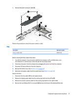
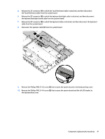
11. Remove the left I/O bracket (3). The left I/O bracket is available using spare part number 829299-001. 12. Lift the left side of the system board (1) until it rests at an angle. 13. Slide the system board (2) up and to the left at an angle until the connectors on the right side of the system board are clear of the openings on the right side of the keyboard/top cover. 14. Swing the rear edge of the system board (3) up and forward until the system board rests upside down on the keyboard/top cover. 42 Chapter 5 Removal and replacement procedures
-
 1
1 -
2
-
3
-
4
-
5
-
6
-
7
-
8
-
9
-
10
-
11
-
12
-
13
-
14
-
15
-
16
-
17
-
18
-
19
-
20
-
21
-
22
-
23
-
24
-
25
-
26
-
27
-
28
-
29
-
30
-
31
-
32
-
33
-
34
-
35
-
36
-
37
-
38
-
39
-
40
-
41
-
42
-
43
-
44
-
45
-
46
-
 47
47 -
 48
48 -
 49
49 -
 50
50 -
 51
51 -
 52
52 -
 53
53 -
 54
54 -
 55
55 -
 56
56 -
 57
57 -
58
-
59
-
60
-
61
-
62
-
63
-
64
-
65
-
66
-
67
-
68
-
69
-
70
-
71
-
72
-
73
-
74
-
75
-
76
-
77
-
78
-
79
-
80
-
81
-
82
 |
 |
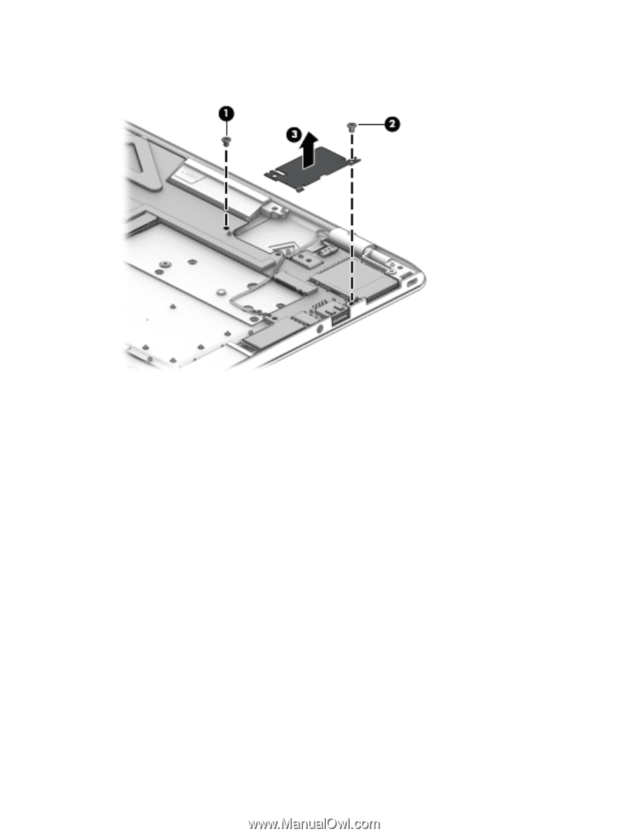
11.
Remove the left I/O bracket
(3)
.
The left I/O bracket is available using spare part number 829299-001.
12.
Lift the left side of the system board
(1)
until it rests at an angle.
13.
Slide the system board
(2)
up and to the left at an angle until the connectors on the right side of the
system board are clear of the openings on the right side of the keyboard/top cover.
14.
Swing the rear edge of the system board
(3)
up and forward until the system board rests upside down on
the keyboard/top cover.
42
Chapter 5
Removal and replacement procedures