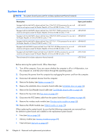
HP ENVY 14t-3000 HP ENVY14 SPECTRE Maintenance and Service Guide IMPORTANT! Th - Page 61
sleeves should be installed on the antenna connectors, as shown in the following illustration.
 |
View all HP ENVY 14t-3000 manuals
Add to My Manuals
Save this manual to your list of manuals |
Page 61 highlights
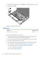
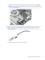
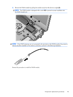
3. Remove the WLAN module by pulling the module away from the slot at an angle (3). NOTE: The WLAN module is designed with a notch (4) to prevent incorrect installation into the WLAN module slot. NOTE: If the WLAN antennas are not connected to the terminals on the WLAN module, the protective sleeves should be installed on the antenna connectors, as shown in the following illustration. Reverse this procedure to install the WLAN module. Component replacement procedures 53
-
 1
1 -
2
-
3
-
4
-
5
-
6
-
7
-
8
-
9
-
10
-
11
-
12
-
13
-
14
-
15
-
16
-
17
-
18
-
19
-
20
-
21
-
22
-
23
-
24
-
25
-
26
-
27
-
28
-
29
-
30
-
31
-
32
-
33
-
34
-
35
-
36
-
37
-
38
-
39
-
40
-
41
-
42
-
43
-
44
-
45
-
46
-
47
-
48
-
49
-
50
-
51
-
52
-
53
-
54
-
55
-
 56
56 -
 57
57 -
 58
58 -
 59
59 -
 60
60 -
 61
61 -
 62
62 -
 63
63 -
 64
64 -
 65
65 -
 66
66 -
67
-
68
-
69
-
70
-
71
-
72
-
73
-
74
-
75
-
76
-
77
-
78
-
79
-
80
-
81
-
82
-
83
-
84
-
85
-
86
-
87
-
88
-
89
-
90
-
91
-
92
-
93
-
94
-
95
-
96
-
97
 |
 |
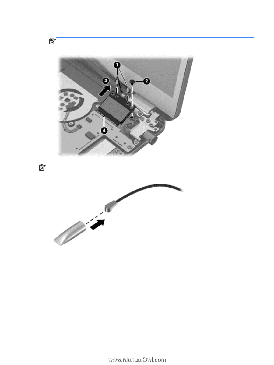
3.
Remove the WLAN module by pulling the module away from the slot at an angle
(3)
.
NOTE:
The WLAN module is designed with a notch
(4)
to prevent incorrect installation into
the WLAN module slot.
NOTE:
If the WLAN antennas are not connected to the terminals on the WLAN module, the protective
sleeves should be installed on the antenna connectors, as shown in the following illustration.
Reverse this procedure to install the WLAN module.
Component replacement procedures
53